Build package
Build Pupper v3
Stanford Student Robotics / Hands-On Robotics · Quadruped · active · 2024
Open-source educational quadruped developed through Stanford courses, with brushless motors, a Raspberry Pi 5 and a reinforcement-learning locomotion policy out of the box.
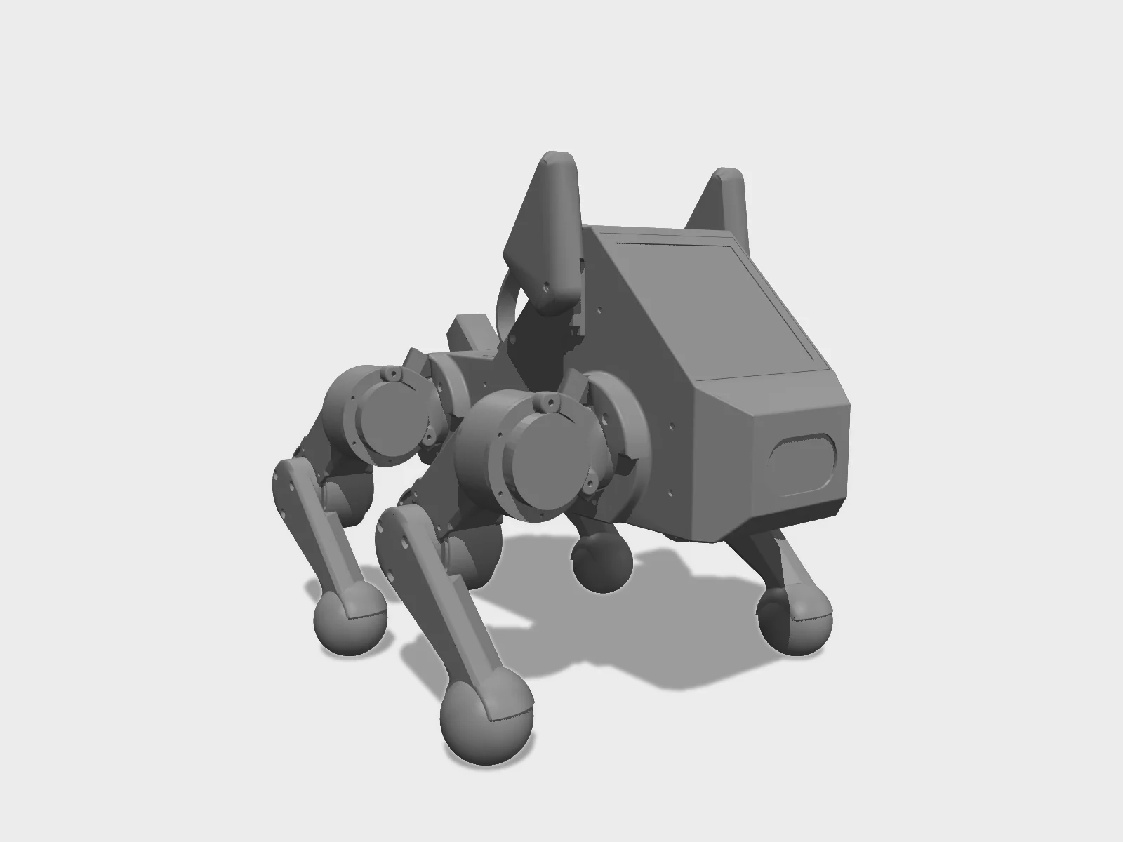
- Drawing
- /stanford/pupper-v3
- Maker
- Stanford Student Robotics / Hands-On Robotics
- Country
- Stanford, US
- Package rev
- v0.1.0
- Level
- L1 Compiled
- Availability
- DIY
- Openness
- 100/100
- HW licence
- unknown
- Last checked
- 2026-09-25
- Mass
- 3 kg
- DOF
- 12
- Actuators
- GIM4305 400 W brushless motors
Ships with an RL locomotion policy. Third-party vendors (e.g. AIFITLAB) sell kits. Year = docs '2024' edition. Licenses (GitHub license API, 2026-09-25): pupper-v3-documentation AGPL-3.0, pupperv3-monorepo and pupperv3-mjx GPL-3.0, pupper_v3_description MIT. CAD is a public Onshape/Fusion share with no stated license. Mass 3 kg per the docs tech specs page.
Configure
Saved in the URL. Share the link to share the build.Source
One cart across 8 vendors · prices in USD as listedStanford Student Robotics / Hands-On Robotics sells this robot. Buying from the maker funds the people who opened the design. No BOM line below lists them as a vendor yet, so check their store before ordering parts one by one.
33 lines · 413 parts · 4 without an offer in US · 4/33 lines sourced in 2+ regions (L3 gate)
| # | Part | Category | Qty | Unit | Line | Offer |
|---|---|---|---|---|---|---|
Amazon11 lines · $395.99 + 1 unpriced | ||||||
| 1 | USB flash drive 128 GB (boot drive for pupOS) compute.usb-128gb | compute | 1 | $14.00list price | $14.00 | AmazonShort link from the BOM |
| 2 | Waveshare 4 x 4 in HDMI Raspberry Pi screen (face display; ships with the HDMI to micro HDMI adapter) electronics.screen-4in | electronics | 1 | $75.99list price | $75.99 | AmazonShort link from the BOM |
| 3 | [Optional] Arducam IMX296 global shutter camera sensor.imx296 · MPN IMX296 | sensor | 1 | $62.00list price | $62.00 | AmazonShort link from the BOM |
| 4 | [Optional] Wireless USB lapel microphone sensor.microphone | sensor | 1 | $12.00list price | $12.00 | AmazonShort link from the BOM |
| 5 | DeWalt 20 V POWERSTACK battery 1.7 Ah power.dewalt-20v | power | 2 | $50.00list price | $100.00 | AmazonBOM line total $100 for 2 |
| 6 | PS5 wireless controller electronics.ps5-controller | electronics | 1 | $75.00list price | $75.00 | AmazonShort link from the BOM |
| 7 | [Optional] Wireless keyboard with trackpad (for first-time setup) electronics.keyboard | electronics | 1 | $28.00list price | $28.00 | AmazonShort link from the BOM |
| 8 | 10-pin JST ZH cable, control board to power board (pin 1 to pin 1) cable.jst-zh-10p | cable | 1 | unpriced | — | AmazonShort link from the BOM |
| 9 | Squash balls, single or double yellow dot (feet) other.squash-balls | other | 4 | $3.75list price | $15.00 | AmazonBOM line total $15 for 4 |
| 10 | Super glue (feet); listed under Tools other.super-glue | other | 1 | $4.00list price | $4.00 | AmazonLoctite Super Glue listing from the BOM |
| 11 | [Optional] Caution hot surface label other.hot-label | other | 1 | $10.00list price | $10.00 | AmazonShort link from the BOM |
DigiKey6 lines · $80.42 + 4 unpriced | ||||||
| 12 | Raspberry Pi 5, 8 GB compute.rpi5-8gb · MPN SC1112 | compute | 1 | $80.00list price | $80.00 | DigiKey |
| 13 | Battery tabs for the distribution board (TE 63849-1) electronics.battery-tabs · MPN 63849-1 | electronics | 2 | $0.21list price | $0.42 | DigiKey |
| 14 | 12" JST ZH pre-crimped wire, for ID 3 (knee) motor cables cable.jst-zh-12in · MPN ASZHSZH28K305 | cable | 24 | unpriced | — | DigiKey |
| 15 | 8" JST ZH pre-crimped wire, for ID 2 (abduction/adduction) motor cables cable.jst-zh-8in · MPN ASZHSZH28K203 | cable | 24 | unpriced | — | DigiKey |
| 16 | 6" JST ZH pre-crimped wire, for ID 1 (hip) motor cables cable.jst-zh-6in · MPN ASZHSZH28K152 | cable | 34 | unpriced | — | DigiKey |
| 17 | 6-pin JST ZH housing (ZHR-6) cable.jst-zh-6p-housing · MPN ZHR-6 · 1 alt | cable | 24 | unpriced | — | DigiKey |
CanaKit1 line · $70.00 | ||||||
| 18 | [Optional] Raspberry Pi AI Kit (Hailo-8L); the build slides install it compute.ai-kit | compute | 1 | $70.00list price | $70.00 | CanaKit |
McMaster-Carr4 lines · $32.00 | ||||||
| 19 | M2.5 x 10 socket head screw (the most-used screw in the build) fastener.m2p5x10 · MPN 91292A014 | fastener | 100 | $0.07list price | $7.00 | McMaster-CarrBOM: $7 for 100 |
| 20 | M2.5 heat-set tapered threaded insert fastener.m2p5-insert · MPN 94180A321 | fastener | 100 | $0.17list price | $17.00 | McMaster-CarrBOM: $17 for 100 |
| 21 | M3 x 8 cap/button head screw (legs, abduction brackets, knob) fastener.m3x8 · MPN 92095A181 | fastener | 50 | $0.08list price | $4.00 | McMaster-CarrBOM: $4 for 50 |
| 22 | M2.5 x 25 socket head screw (control board to brain bracket; listed under 'Stand' in the BOM) fastener.m2p5x25 · MPN 91292A036 | fastener | 4 | $1.00list price | $4.00 | McMaster-CarrBOM: $4 for 4 |
Bambu Lab US store1 line · $20.00 | ||||||
| 23 | Bambu PETG HF 1.75 mm filament for the structure printed.petg-hf | printed | 1 | $20.00list price | $20.00 | Bambu Lab US store |
Adafruit3 lines · $18.50 | ||||||
| 24 | 2x20 female header extension electronics.header-2x20 | electronics | 1 | $2.50list price | $2.50 | Adafruit |
| 25 | [Optional] Speaker electronics.speaker | electronics | 1 | $4.00list price | $4.00 | Adafruit |
| 26 | [Optional] Ear servos (9 g micro servo) actuator.ear-servo | actuator | 2 | $6.00list price | $12.00 | Adafruit |
UCTronics2 lines · $18.00 | ||||||
| 27 | [Optional] M12 fisheye lens sensor.fisheye-lens · MPN M32076M20 | sensor | 1 | $15.00list price | $15.00 | UCTronics |
| 28 | [Optional] M12 small metal lens holder sensor.lens-holder | sensor | 1 | $3.00list price | $3.00 | UCTronics |
Waveshare1 line · $13.00 | ||||||
| 29 | [Optional] Waveshare PCIe to M.2 board (E) for the AI kit electronics.m2-adapter | electronics | 1 | $13.00list price | $13.00 | Waveshareships globally |
No offer in this region4 lines · $1,395.00 + 1 unpriced | ||||||
| 30 | Steadywin GIM4305 with SHS driver (select the 'Pupper v3 version' so drivers come pre-flashed) actuator.gim4305 · MPN GIM4305 | actuator | 12 | $110.00list price | $1,320.00 | Offers in CN only |
| 31 | Pi hat control board Rev 3.5 (custom PCBA, needs a BNO086 IMU; firmware SPIneV1) electronics.control-board | electronics | 1 | $60.00list price | $60.00 | Offers in CN only |
| 32 | Power distribution board Rev 3.5 (custom PCB) electronics.power-board | electronics | 1 | $15.00list price | $15.00 | Offers in CN only |
| 33 | 10 mm braided cable sleeving (24-25 cm segments for 12" cables, 13-14 cm for the shorter leg cables) cable.sleeving-10mm | cable | 12 | unpriced | — | No offer found yet |
| Cart total · US | 413 | $2,042.91 | 6 lines unpriced, not in total | |||
Fabricate
Planned for a 256 mm bed- Fabricated parts
- 30
- Print time (sum)
- —
- Material (sum)
- —
- Plates · estimate
- —
No plate estimate: the package does not list grams per part yet, and we will not guess them. Slice the source files for your 256 mm bed.
| Part | Process | Material | Qty | h / part | g / part | Profile |
|---|---|---|---|---|---|---|
Upper body (top half.stl) printed.upper-body | FDM | PETG | 1 | — | — | PETG, 15% infill, 3 walls, 0.3 mm layers, 0.6 mm nozzle, tree supports on build plate (auto) |
Lower body (bottom half.stl) printed.lower-body | FDM | PETG | 1 | — | — | PETG, 15% infill, 3 walls, 0.3 mm layers, 0.6 mm nozzle, no supports |
Brain bracket (brain.stl) printed.brain-bracket | FDM | PETG | 1 | — | — | PETG, 15% infill, 3 walls, 0.3 mm layers, 0.6 mm nozzle, tree supports on build plate (auto) |
Power distribution board cover (top tray.stl) printed.pdb-cover | FDM | PETG | 1 | — | — | PETG, 15% infill, 3 walls, 0.3 mm layers, 0.6 mm nozzle, no supports |
Ear, right (skinny_ear_right.stl) printed.ear-rh | FDM | PETG | 1 | — | — | PETG, 10% infill, 2 walls, 0.3 mm layers, 0.6 mm nozzle, no supports |
Ear, left (skinny_ear_left.stl) printed.ear-lh | FDM | PETG | 1 | — | — | PETG, 10% infill, 2 walls, 0.3 mm layers, 0.6 mm nozzle, no supports |
Front cable clamp, RH and LH (front_cable_clamp.stl) printed.front-clamp | FDM | PETG | 1 | — | — | PETG, 15% infill, 3 walls, 0.3 mm layers, 0.6 mm nozzle, no supports |
Back cable clamp (back_clamp.stl) printed.back-clamp | FDM | PETG | 2 | — | — | PETG, 15% infill, 3 walls, 0.3 mm layers, 0.6 mm nozzle, no supports |
Strap / handle (strap.stl) printed.strap | FDM | TPU | 1 | — | — | TPU, 100% infill, 20 walls, 0.3 mm layers, 0.6 mm nozzle, no supports |
Lower leg, right (lower_leg_right.stl) printed.lower-leg-rh | FDM | PETG | 2 | — | — | PETG, 15% infill, 3 walls, 0.3 mm layers, 0.6 mm nozzle, no supports |
Lower leg, left (lower_leg_left.stl) printed.lower-leg-lh | FDM | PETG | 2 | — | — | PETG, 15% infill, 3 walls, 0.3 mm layers, 0.6 mm nozzle, no supports |
Upper leg, right (thigh_right.stl) printed.thigh-rh | FDM | PETG | 2 | — | — | PETG, 15% infill, 3 walls, 0.3 mm layers, 0.6 mm nozzle, tree supports on build plate (auto) |
Upper leg, left (thigh_left.stl) printed.thigh-lh | FDM | PETG | 2 | — | — | PETG, 15% infill, 3 walls, 0.3 mm layers, 0.6 mm nozzle, tree supports on build plate (auto) |
Upper leg motor bracket / leg cable cover, RH and LH (upper_leg_bracket.stl) printed.upper-leg-bracket | FDM | PETG | 2 | — | — | PETG, 15% infill, 3 walls, 0.3 mm layers, 0.6 mm nozzle, no supports |
Hip shroud / joint cover, RH and LH (shroud.stl) printed.hip-shroud | FDM | PETG | 4 | — | — | PETG, 15% infill, 3 walls, 0.3 mm layers, 0.6 mm nozzle, no supports |
Hip (abduction) bracket, right (hip_bracket_shroud_right.stl) printed.hip-bracket-rh | FDM | PETG | 2 | — | — | PETG, 15% infill, 3 walls, 0.3 mm layers, 0.6 mm nozzle, tree supports on build plate (auto, hybrid) |
Hip (abduction) bracket, left (hip_bracket_shroud_left.stl) printed.hip-bracket-lh | FDM | PETG | 2 | — | — | PETG, 15% infill, 3 walls, 0.3 mm layers, 0.6 mm nozzle, tree supports on build plate (auto, hybrid) |
[Optional] Stand printed.stand | FDM | PETG | 1 | — | — | PETG, 15% infill, 3 walls, 0.3 mm layers, 0.6 mm nozzle, no supports (no STL link in the BOM row) |
[Optional] Stand base plate (stand_base.dxf), BOM ~$80 via SendCutSend sheet.stand-base | Laser | Stainless steel 304, 0.125 in | 1 | — | — | SendCutSend: 0.125 in SS304, tap M3x0.5 on the small holes and M6x1 on the larger holes |
Assemble
Every step ends in a check- Steps
- 21
- Subassemblies
- 9
- Hands-on time (sum)
- —
- Critical path
- —
- Your progress · this device
- —
21 steps have no time estimate; times above are lower bounds.
Steps, in build order
- Electronics prep01
Order the control board and power board
Download the Rev 3.5 manufacturing files linked in the BOM. Use JLCPCB's global sourcing to get the BNO086 IMU into your JLCPCB parts inventory (it is not in their local stock), then place a PCBA order for both boards with those files.
CHECKAssembled control board (with BNO086) and power board delivered; the control board has two MCUs and the pogo pins for the Pi header.- Parts in
- Pi hat control board Rev 3.5 (custom PCBA, needs a BNO086 IMU; firmware SPIneV1)electronics.control-board
- Power distribution board Rev 3.5 (custom PCB)electronics.power-board
- Tools
- —
- Torque
- —
- Time
- —
- After
- Start
- Fabrication02
Print the body, legs, brackets and strap
PETG at 15% infill, 3 walls, 0.3 mm layers, 0.6 mm nozzle; tree supports on the build plate only for the upper body, brain bracket, thighs and hip brackets. Ears at 10% infill and 2 walls. Strap in TPU at 100% infill, 20 walls.
CHECKAll parts per the BOM counts (left/right legs and brackets in pairs); support removed cleanly from screw bosses.- Parts in
- Bambu PETG HF 1.75 mm filament for the structureprinted.petg-hf
- Upper body (top half.stl)printed.upper-body
- Lower body (bottom half.stl)printed.lower-body
- Brain bracket (brain.stl)printed.brain-bracket
- Power distribution board cover (top tray.stl)printed.pdb-cover
- Ear, right (skinny_ear_right.stl)printed.ear-rh
- Ear, left (skinny_ear_left.stl)printed.ear-lh
- Front cable clamp, RH and LH (front_cable_clamp.stl)printed.front-clamp
- Back cable clamp (back_clamp.stl)printed.back-clamp
- Strap / handle (strap.stl)printed.strap
- Lower leg, right (lower_leg_right.stl)printed.lower-leg-rh
- Lower leg, left (lower_leg_left.stl)printed.lower-leg-lh
- Upper leg, right (thigh_right.stl)printed.thigh-rh
- Upper leg, left (thigh_left.stl)printed.thigh-lh
- Upper leg motor bracket / leg cable cover, RH and LH (upper_leg_bracket.stl)printed.upper-leg-bracket
- Hip shroud / joint cover, RH and LH (shroud.stl)printed.hip-shroud
- Hip (abduction) bracket, right (hip_bracket_shroud_right.stl)printed.hip-bracket-rh
- Hip (abduction) bracket, left (hip_bracket_shroud_left.stl)printed.hip-bracket-lh
- Tools
- FDM printer with a 0.6 mm nozzle
- Torque
- —
- Time
- —
- After
- Start
- Source
- docs.google.com
- Software03
Flash pupOS to the USB drive
Download the full image `pupOS_pios_full_[version]` from the docs' Google Drive folder. In Imager: device Raspberry Pi 5, 'Use custom' OS, your USB drive, then Edit Settings: hostname `pupper`, username `pi`, your password (default in the docs `rhea123`), Wi-Fi (skip for captive-portal networks), enable SSH with password authentication. Write.
CHECKImager finishes verification with no error.- Parts in
- USB flash drive 128 GB (boot drive for pupOS)compute.usb-128gb
- Tools
- Raspberry Pi Imager 1.8.5 (not Balena Etcher; 1.9.6 is noted as broken)
- Torque
- —
- Time
- —
- After
- Start
- Electronics prep04
Flash both MCUs on the control board with SPIneV1
Make a 7-pin JST SH cable to the pinout in the slides and connect VCC, TCK (SWCLK), GND and TMS (SWDIO) to the ST-Link V2. In STM32CubeProgrammer click 'Open file', select `SPIneV1.elf` (Drive link on the docs page), click 'Download'. Repeat for the second MCU.
CHECKSTM32CubeProgrammer reports a successful download for both MCUs.- Parts in
- Pi hat control board Rev 3.5 (custom PCBA, needs a BNO086 IMU; firmware SPIneV1)electronics.control-board
- Tools
- ST-Link V2, JST SH kit to make a 7-pin cable, STM32CubeProgrammer
- Torque
- —
- Time
- —
- After
- 01
- 05
Flash and configure the 12 motor drivers (skip if bought as 'Pupper v3 version')
Safety · human-verified requiredFlash: wire the JST SH cable to the ST-Link (check the order twice), plug it into the motor's right connector, open the firmware .elf in STM32CubeProgrammer and click Download. Configure: install the CP2102 driver, plug the 4-pin cable (yellow GND, black TXD, blue RXD, red not connected) into the motor's left connector, power the motor from the Pupper power board and battery, run `steadywin_motor_wizard_*.exe`, set the parameters and CAN ID (1 hip, 2 abduction, 3 knee per leg), calibrate the encoder, then click Sync. The doc's author recommends an 8 A max current rather than 12 A.
CHECKMotor Wizard connects, shows the saved ID and parameters after Sync, and the GUI can spin the unloaded motor in speed/position mode.This step can hurt a person or ruin parts. Its instructions need sign-off by a human who has done it before relying on them. Stop and ask if anything differs from what you see.
- Parts in
- Steadywin GIM4305 with SHS driver (select the 'Pupper v3 version' so drivers come pre-flashed)actuator.gim4305
- Power distribution board Rev 3.5 (custom PCB)electronics.power-board
- DeWalt 20 V POWERSTACK battery 1.7 Ahpower.dewalt-20v
- Tools
- ST-Link V2, 3/4-pin JST SH cable, CP2102 USB-UART adapter (must be CP2102), Windows PC with Steadywin Motor Wizard, STM32CubeProgrammer
- Torque
- —
- Time
- —
- After
- 01
- Source
- docs.google.com
- Fabrication06
Heat-set inserts and squash-ball feet
Safety · human-verified requiredInsert the M2.5 threaded inserts into all the insert holes of the printed parts with the iron at 250 °C. Glue a squash ball onto each lower leg with super glue.
CHECKInserts flush and square; each squash ball bonded and does not twist off by hand once cured.This step can hurt a person or ruin parts. Its instructions need sign-off by a human who has done it before relying on them. Stop and ask if anything differs from what you see.
- Parts in
- M2.5 heat-set tapered threaded insertfastener.m2p5-insert
- Squash balls, single or double yellow dot (feet)other.squash-balls
- Super glue (feet); listed under Toolsother.super-glue
- Lower leg, right (lower_leg_right.stl)printed.lower-leg-rh
- Lower leg, left (lower_leg_left.stl)printed.lower-leg-lh
- Tools
- Soldering iron at 250 °C
- Torque
- —
- Time
- —
- After
- 02
- Brain07
Brain: Pi 5, AI kit, header, screen, camera, control board, speaker
Stick the thermal pads on the Pi, mount the M.2 adapter/cooler with its screws and connect its fan and ribbon cables. Move the Hailo module from its original board to the adapter (use the adapter's thumbscrew, hand-tight). Press the 2x20 header extension on (push the black plastic, not the pins). Seat the screen's HDMI adapter and pogo pins. Connect the camera ribbon (about 2 mm of blue visible) and screw the camera to the brain bracket with 4 M2.5x10. Fix the bracket to the Pi, then the control board with 4 M2.5x25 so its pogo pins land on the Pi pins (loosen 4 turns and realign if not). Speaker on with 2 M2.5x10, cables behind it. USB stick into a blue USB 3 port.
CHECKPogo pins touch the Pi header from every angle; ribbon latches are closed; USB drive is in a blue port.- Parts in
- Raspberry Pi 5, 8 GBcompute.rpi5-8gb
- [Optional] Raspberry Pi AI Kit (Hailo-8L); the build slides install itcompute.ai-kit
- [Optional] Waveshare PCIe to M.2 board (E) for the AI kitelectronics.m2-adapter
- 2x20 female header extensionelectronics.header-2x20
- Waveshare 4 x 4 in HDMI Raspberry Pi screen (face display; ships with the HDMI to micro HDMI adapter)electronics.screen-4in
- [Optional] Arducam IMX296 global shutter camerasensor.imx296
- Brain bracket (brain.stl)printed.brain-bracket
- Pi hat control board Rev 3.5 (custom PCBA, needs a BNO086 IMU; firmware SPIneV1)electronics.control-board
- M2.5 x 10 socket head screw (the most-used screw in the build)fastener.m2p5x10
- M2.5 x 25 socket head screw (control board to brain bracket; listed under 'Stand' in the BOM)fastener.m2p5x25
- [Optional] Speakerelectronics.speaker
- USB flash drive 128 GB (boot drive for pupOS)compute.usb-128gb
- Tools
- Phillips screwdriver, Electric screwdriver (BOM Tools)
- Torque
- —
- Time
- —
- Source
- docs.google.com
- Legs08
Build 4 legs (motors ID 3 and ID 2)
Sleeve and connect a 12" cable to motor ID 3 and an 8" cable to motor ID 2, covered end flush at the motor, pin 1 to pin 1. Lower leg to motor 3 with 3 M3x8 (align all three before tightening). Upper leg on motor 3 with its slot under the cable; remove the motor screw that blocks the leg, then 2 M2.5x10 on that side and the leg cable cover with 4 M2.5x10 on the other. Abduction bracket to motor 3 with 3 M3x8, motor 2 cable under the bracket's cable block. Remove the blocking screw on motor 2, fix the bracket with 2 M2.5 screws each side (tighten only when all 4 are in), then upper leg to motor 2 with 3 M3x8. Check L/R labels on every part.
CHECKFour legs, two left and two right, with ID 3 and ID 2 cables sleeved flush at the motor and every joint turning without rubbing.- Parts in
- 12" JST ZH pre-crimped wire, for ID 3 (knee) motor cablescable.jst-zh-12in
- 8" JST ZH pre-crimped wire, for ID 2 (abduction/adduction) motor cablescable.jst-zh-8in
- 6-pin JST ZH housing (ZHR-6)cable.jst-zh-6p-housing
- 10 mm braided cable sleeving (24-25 cm segments for 12" cables, 13-14 cm for the shorter leg cables)cable.sleeving-10mm
- Steadywin GIM4305 with SHS driver (select the 'Pupper v3 version' so drivers come pre-flashed)actuator.gim4305
- Lower leg, right (lower_leg_right.stl)printed.lower-leg-rh
- Lower leg, left (lower_leg_left.stl)printed.lower-leg-lh
- Upper leg, right (thigh_right.stl)printed.thigh-rh
- Upper leg, left (thigh_left.stl)printed.thigh-lh
- Upper leg motor bracket / leg cable cover, RH and LH (upper_leg_bracket.stl)printed.upper-leg-bracket
- Hip (abduction) bracket, right (hip_bracket_shroud_right.stl)printed.hip-bracket-rh
- Hip (abduction) bracket, left (hip_bracket_shroud_left.stl)printed.hip-bracket-lh
- M3 x 8 cap/button head screw (legs, abduction brackets, knob)fastener.m3x8
- M2.5 x 10 socket head screw (the most-used screw in the build)fastener.m2p5x10
- Tools
- Phillips screwdriver, Electric screwdriver
- Torque
- —
- Time
- —
- Source
- docs.google.com
- Brain09
Fisheye lens swap and focus
Replace the camera's lens holder with the short holder and the fisheye lens. With the Pi running, view the feed with `rpicam-hello -t 60s` and turn the lens until the image is sharp.
CHECKThe rpicam-hello preview is in focus.- Parts in
- [Optional] M12 fisheye lenssensor.fisheye-lens
- [Optional] M12 small metal lens holdersensor.lens-holder
- [Optional] Arducam IMX296 global shutter camerasensor.imx296
- Tools
- —
- Torque
- —
- Time
- —
- After
- 07
- 10
Brain bench test on USB-C power
Power the Pi from USB-C; it should reach the PiOS desktop in 30-60 s. Open a terminal: `sudo systemctl stop robot`, then `rpicam-hello` (camera), `sudo lspci` (Hailo 8L), and `speaker-test` with the volume up.
CHECKScreen shows the desktop; rpicam-hello opens a preview; the Hailo accelerator appears in lspci; speaker-test plays white noise. If the screen stays dark: reseat power, the HDMI adapter and the display.- Parts in
- —
- Tools
- USB-C 5 V supply, Mouse and keyboard
- Torque
- —
- Time
- —
- After
- 07
- Source
- docs.google.com
- Body11
Body: ear servos, brain, power board, front hip motors (ID 1)
Fix each ear servo to the upper body with an M2.5x10 through its bottom hole, cable up. Put the brain in and fix the electronics tray with 2 M2.5x10 per side (screen flush with the body edges). Plug the ear servos into the L and R servo headers. Connect the 10-pin cable (pin 1 to pin 1) to the power board, mount the board with only its 2 top screws, and plug the other end into the control board. Make 6-pin ID 1 cables (pin 1 to pin 1) from the 6" wires, connect two ID 1 motors, and fix them with 2 M2.5x10 each, cables toward the control board; plug left to left, right to right.
CHECKBoth front hip motors are fixed with cables pointing at the control board and plugged into matching ports; the 10-pin cable is fully seated at both ends.- Parts in
- [Optional] Ear servos (9 g micro servo)actuator.ear-servo
- Upper body (top half.stl)printed.upper-body
- 10-pin JST ZH cable, control board to power board (pin 1 to pin 1)cable.jst-zh-10p
- Power distribution board Rev 3.5 (custom PCB)electronics.power-board
- Battery tabs for the distribution board (TE 63849-1)electronics.battery-tabs
- 6" JST ZH pre-crimped wire, for ID 1 (hip) motor cablescable.jst-zh-6in
- 6-pin JST ZH housing (ZHR-6)cable.jst-zh-6p-housing
- Steadywin GIM4305 with SHS driver (select the 'Pupper v3 version' so drivers come pre-flashed)actuator.gim4305
- M2.5 x 10 socket head screw (the most-used screw in the build)fastener.m2p5x10
- Tools
- Electric screwdriver
- Torque
- —
- Time
- —
- Source
- docs.google.com
- 12
Body: temporary cover, bottom half, knob
Fit the power board cover with 4 of its 6 M2.5x10 (it comes off again for the rear motor cables). Attach the bottom body to the top with 4 M2.5x10. Attach the knob with 3 M3x8.
CHECKCover and bottom half sit flush; no cable is pinched at the screw holes.- Parts in
- Power distribution board cover (top tray.stl)printed.pdb-cover
- Lower body (bottom half.stl)printed.lower-body
- M2.5 x 10 socket head screw (the most-used screw in the build)fastener.m2p5x10
- M3 x 8 cap/button head screw (legs, abduction brackets, knob)fastener.m3x8
- Tools
- —
- Torque
- —
- Time
- —
- After
- 11
- Source
- docs.google.com
- 13
First battery power-up
Safety · human-verified requiredLine the power board tabs up with the battery slots and push the DeWalt pack in until it clicks; it must not stick out below the body. Press the power button (it stays down). Keep hands clear of the front hip motors. Press again to turn off.
CHECKScreen turns on and the two front motors rotate slowly. If not: push the battery fully in and check its charge (button on the pack); for motors, re-check the USB image and motor CAN IDs.This step can hurt a person or ruin parts. Its instructions need sign-off by a human who has done it before relying on them. Stop and ask if anything differs from what you see.
- Parts in
- DeWalt 20 V POWERSTACK battery 1.7 Ahpower.dewalt-20v
- Tools
- —
- Torque
- —
- Time
- —
- After
- 12
- Source
- docs.google.com
- Legs14
Mount the front legs and set cable slack
Route the motor 3 and motor 2 cables through the side hole of the upper body into the tan connectors, motor 2 cable on top, not twisted. Fit the front cable clamp with 2 M2.5x10 loose, rotate the abduction bracket to its clockwise stop and back to pull through the right slack, then tighten. Tuck cables away from the cover screw holes. Repeat on the other side.
CHECKEach front hip rotates fully forward and back without pulling on its wires.- Parts in
- Front cable clamp, RH and LH (front_cable_clamp.stl)printed.front-clamp
- M2.5 x 10 socket head screw (the most-used screw in the build)fastener.m2p5x10
- Tools
- —
- Torque
- —
- Time
- —
- Source
- docs.google.com
- 15
Mount the back hip motors (ID 1) and legs
Connect a 6" cable to each rear motor 1, fix it to the body with 2 M2.5x10, plug it into the power board. Abduction bracket onto motor 1 with 3 M3x8 (left bracket on the left side). Install motor 2 with the same screw removal and routing as the front, attach the leg with 3 M3x8, route both cables through the slot into the two power board connectors (either order). Back cable clamp with 2 M2.5x10, set slack as at the front, then tighten.
CHECKEach rear hip rotates fully before the clamp is tightened and the cables do not pull.- Parts in
- 6" JST ZH pre-crimped wire, for ID 1 (hip) motor cablescable.jst-zh-6in
- Steadywin GIM4305 with SHS driver (select the 'Pupper v3 version' so drivers come pre-flashed)actuator.gim4305
- Hip (abduction) bracket, right (hip_bracket_shroud_right.stl)printed.hip-bracket-rh
- Hip (abduction) bracket, left (hip_bracket_shroud_left.stl)printed.hip-bracket-lh
- Back cable clamp (back_clamp.stl)printed.back-clamp
- M2.5 x 10 socket head screw (the most-used screw in the build)fastener.m2p5x10
- M3 x 8 cap/button head screw (legs, abduction brackets, knob)fastener.m3x8
- Tools
- —
- Torque
- —
- Time
- —
- After
- 14
- Source
- docs.google.com
- Body16
Strap, cover, bottom, joint covers, ears
Screw the TPU strap to the power board cover with 4 M2.5x10, then fix the cover with all 6 M2.5x10. Attach the bottom body with 4 M2.5x10 per side. Slide each joint cover bracket (hip shroud) into position until it locks. Fit the ears on the ear servos with the small servo screws. Optionally add the hot-surface label.
CHECKAll 6 cover screws in; shrouds locked; lift the robot only by the strap.- Parts in
- Strap / handle (strap.stl)printed.strap
- Power distribution board cover (top tray.stl)printed.pdb-cover
- Lower body (bottom half.stl)printed.lower-body
- Hip shroud / joint cover, RH and LH (shroud.stl)printed.hip-shroud
- Ear, right (skinny_ear_right.stl)printed.ear-rh
- Ear, left (skinny_ear_left.stl)printed.ear-lh
- [Optional] Ear servos (9 g micro servo)actuator.ear-servo
- M2.5 x 10 socket head screw (the most-used screw in the build)fastener.m2p5x10
- [Optional] Caution hot surface labelother.hot-label
- Tools
- —
- Torque
- —
- Time
- —
- After
- 15
- Source
- docs.google.com
- Software17
First boot and PS5 controller pairing
Power on. Pair the PS5 pad: either use the PiOS Bluetooth menu with a mouse, or SSH in (`ssh pi@pupper.local`) and run `sudo ~/pupperv3-monorepo/robot/utils/pair_ps5_controller.sh` while holding Create + PS on the pad until it flashes.
CHECKThe controller shows solid blue lights and a white light above the PS logo.- Parts in
- PS5 wireless controllerelectronics.ps5-controller
- [Optional] Wireless keyboard with trackpad (for first-time setup)electronics.keyboard
- Tools
- —
- Torque
- —
- Time
- —
- After
- 16
- Bring-up18
First run: homing and RL walking policy
Safety · human-verified requiredRobot on the floor, not on a table. Power on with the switch on the back; the stack starts automatically and each leg drives to its end stops, then to a rest pose (homing). Turn on the controller, wait a few seconds after homing, then press the 'release e-stop' button to start the walking policy. The back switch is the E-STOP. There is no hardware low-voltage cutoff: stop within about 40 minutes and check the pack's gauge.
CHECKLegs home and settle to rest; after e-stop release the robot stands and walks with the sticks; the back switch cuts power at once.This step can hurt a person or ruin parts. Its instructions need sign-off by a human who has done it before relying on them. Stop and ask if anything differs from what you see.
- Parts in
- DeWalt 20 V POWERSTACK battery 1.7 Ahpower.dewalt-20v
- Tools
- —
- Torque
- —
- Time
- —
- After
- 17
- Software19
Optional: development mode and MuJoCo sim
SSH in, `sudo systemctl disable robot`, `sudo chown -R pi /home/pi`, then `cd ~/pupperv3-monorepo/ros2_ws` and `./build.sh`. Run `ros2 launch neural_controller launch.py sim:=True` for the MuJoCo sim or `ros2 launch neural_controller launch.py` on hardware. If neural_controller is not found, rebuild and `source ~/pupperv3-monorepo/ros2_ws/install/local_setup.bash`.
CHECKsim:=True opens a MuJoCo window with Pupper; the hardware launch reproduces the auto-start behaviour.- Parts in
- —
- Tools
- —
- Torque
- —
- Time
- —
- After
- 18
- Options20
Optional: display stand and microphone
Print the stand in PETG and have the stand base cut by SendCutSend from stand_base.dxf (0.125 in SS304, M3x0.5 taps on the small holes, M6x1 on the larger). The BOM groups four M2.5x25 screws under 'Stand'. Plug the wireless lapel microphone's USB receiver into the Pi for voice interaction. Neither the slides nor the docs give assembly steps for these.
CHECKRobot sits on the stand with the feet off the ground; the microphone shows up as an audio input on the Pi.- Parts in
- [Optional] Standprinted.stand
- [Optional] Stand base plate (stand_base.dxf), BOM ~$80 via SendCutSendsheet.stand-base
- M2.5 x 25 socket head screw (control board to brain bracket; listed under 'Stand' in the BOM)fastener.m2p5x25
- [Optional] Wireless USB lapel microphonesensor.microphone
- Tools
- —
- Torque
- —
- Time
- —
- After
- 18
- Source
- docs.google.com
- Policy21
Optional: train and deploy a new policy
Train with the docs' Colab notebook (built on pupperv3-mjx: MuJoCo MJX + Brax). Download the resulting .json policy from the W&B run into `neural_controller/launch`, point `model_path` in `neural_controller/launch/config.yaml` at it, `./build.sh`, test with `sim:=True`, then run on hardware.
CHECKThe new policy walks in sim before you put it on the robot.- Parts in
- —
- Tools
- Google Colab GPU, Weights & Biases account
- Torque
- —
- Time
- —
- After
- 19
Progress is stored in this browser only (localStorage). Nothing is sent anywhere.
Bring-up
Flash · calibrate · first policy- A
Flash firmware
TargetsControl board Rev 3.5, two STM32 MCUs: SPIneV1.elf via ST-Link V2 / STM32CubeProgrammer, 12 x Steadywin GIM4305 SHS drivers: vendor firmware .elf via ST-Link, parameters and CAN ID via Steadywin Motor Wizard over CP2102 UART, Raspberry Pi 5: pupOS image (PiOS + ROS 2 Jazzy + pupperv3-monorepo)
Repogithub.com/Nate711/pupperv3-monorepo
Firmware binaries (SPIneV1.elf, motor .elf, Motor Wizard .exe) are Google Drive downloads, not source in a repo. The Pi runs ROS 2 (neural_controller, control_board_hardware_interface over SPI to the control board, which talks CAN to the motors). robot.service runs `ros2 launch neural_controller launch.py` at boot.
- B
Calibrate
CalibrationMotor encoders: 'calibrate encoder' then Sync in Motor Wizard during driver setup. Joint zero: automatic at every start; control_board_hardware_interface drives each joint to its end stop (homing stages, velocities and torque thresholds from the ros2_control xacro) and then to the rest pose.Log the output. It goes in your build report.
- C
First policy
- velocity-tracking locomotion from joystick (default walking policy)MuJoCo MJX + Brax PPO (pupperv3-mjx), JSON weights run by the neural_controller ROS 2 node source
- three-legged walkingMuJoCo MJX + Brax PPO (pupperv3-mjx) source
Try the policy in the browser sim before it touches hardware. Keep a hand near the power switch the first time a policy runs on the real robot.
Report your build
Moves Pupper v3 toward L4 · BuiltA build report is the only thing that proves a package works. It raises the level, puts a point on the map, and tells the Foreman which steps to rewrite.
Level gate
Holds L1 · evidence, not confidence- L0Indexed
Known to exist. Atlas page only.
- 6 sources on record(met)
- L1Compiled
Package validates against the spec; every fact has a source.
- Build package compiled(met)
- 25 sources across robot and package(met)
- L2Sim-verified
Loads in browser and GPU sim, mass within tolerance of the BOM, holds a stand. Unlocks .training.
- URDF/MJCF is public(met)
- Sim load, mass tolerance and stand are checked on .training(checked elsewhere)
- L3Sourced
Every BOM line resolves to a live offer in at least two regions. Unlocks the one-click cart.
- 3/33 BOM lines have offers in 2+ regions(not met)
- L4Built
At least one community build report with photos and bring-up logs. Unlocks Build it as the main action.
- 0 reviewed build reports(not met)
- Review feed unreachable at last refresh; count is registry-only(checked elsewhere)
- L5Certified
The robot's maintainer signs the package. Unlocks certified teams and kit sales.
- Maintainer signature not recorded(not met)
Levels are cumulative and set by the registry from reviewed evidence. This panel shows what can be measured from the package today.
Same robot, other verbs
Revisions and sources
Every fact on this sheet traces to one of these| Rev | Description | Checked |
|---|---|---|
| PKG | Build package, current revision 0.1.0 | — |
| S1 | Pupper v3 docs: technical specifications (3 kg)pupper-v3-documentation.readthedocs.io | 2026-09-25 |
| S2 | pupperv3-monorepo (ROS 2 stack, policies; GPL-3.0)github.com | 2026-09-25 |
| S3 | pupperv3-mjx (MJX training; GPL-3.0)github.com | 2026-09-25 |
| S4 | Pupper v3 docs: modifying code, training a policypupper-v3-documentation.readthedocs.io | 2026-09-25 |
| S5 | Pupper v3 documentationpupper-v3-documentation.readthedocs.io | 2026-09-24 |
| S6 | README: Pupper v3 quick specsgithub.com | 2026-09-24 |
| S7 | Pupper v3 documentation (index)pupper-v3-documentation.readthedocs.io | 2026-09-25 |
| S8 | Pupper v3 docs: sourcing partspupper-v3-documentation.readthedocs.io | 2026-09-25 |
| S9 | Pupper v3 bill of materials (Google Sheets, tab v3.5)docs.google.com | 2026-09-25 |
| S10 | Pupper v3 docs: buildingpupper-v3-documentation.readthedocs.io | 2026-09-25 |
| S11 | Pupper Build Instructions (Google Slides)docs.google.com | 2026-09-25 |
| S12 | Motor driver flashing and configuration (Google Doc)docs.google.com | 2026-09-25 |
| S13 | Pupper v3 docs: flashing the control boardpupper-v3-documentation.readthedocs.io | 2026-09-25 |
| S14 | Pupper v3 docs: OS installation and first-time setuppupper-v3-documentation.readthedocs.io | 2026-09-25 |
| S15 | Pupper v3 docs: operationpupper-v3-documentation.readthedocs.io | 2026-09-25 |
| S16 | Pupper v3 docs: safetypupper-v3-documentation.readthedocs.io | 2026-09-25 |
| S17 | Pupper v3 docs: modifying code, training a policypupper-v3-documentation.readthedocs.io | 2026-09-25 |
| S18 | Pupper v3 docs: technical specificationspupper-v3-documentation.readthedocs.io | 2026-09-25 |
| S19 | pupper-v3-documentation repogithub.com | 2026-09-25 |
| S20 | pupperv3-monorepo (ROS 2 stack, policies)github.com | 2026-09-25 |
| S21 | pupperv3-mjx (MJX/Brax training environment)github.com | 2026-09-25 |
| S22 | pupper_v3_description (URDF/xacro, MuJoCo XML)github.com | 2026-09-25 |
| S23 | Present Perfection Pupper v3 full kitpresent-perfection.com | 2026-09-25 |
| S24 | AIFitLab Pupper v3 kitaifitlab.com | 2026-09-25 |
| S25 | Stanford CS 123 course sitecs123-stanford.readthedocs.io | 2026-09-25 |