Build package
Build AmazingHand
Pollen Robotics · Hand · active · 2025
Fully 3D-printable 8-DOF four-finger humanoid hand with all actuators inside the hand, designed for Pollen's Reachy2 wrist but adaptable.
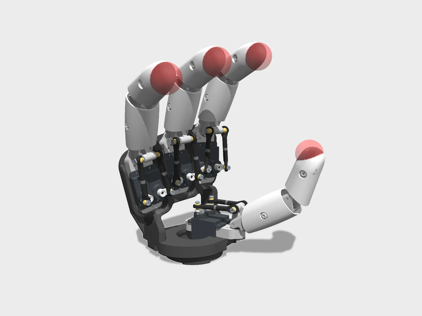
- Drawing
- /pollen/amazing-hand
- Maker
- Pollen Robotics
- Country
- Bordeaux, FR
- Package rev
- v0.1.0
- Level
- L1 Compiled
- Availability
- DIY
- Openness
- 90/100
- HW licence
- CC-BY-4.0
- Last checked
- 2026-09-25
- Mass
- 0.4 kg
- DOF
- 8
- Actuators
- 8x Feetech SCS0009 servos (2 per finger)
An 'Amazing Hand Enhanced' branch exists. Third-party kits from WowRobo/Seeed. Onshape CAD public. Left and right MJCF models ship in Demo/AHSimulation.
Configure
Saved in the URL. Share the link to share the build.Source
One cart across 0 vendors · prices in USD as listedPollen Robotics sells this robot. Buying from the maker funds the people who opened the design. No BOM line below lists them as a vendor yet, so check their store before ordering parts one by one.
15 lines · 105 parts · 15 without an offer in US · 0/15 lines sourced in 2+ regions (L3 gate)
| # | Part | Category | Qty | Unit | Line | Offer |
|---|---|---|---|---|---|---|
No offer in this region15 lines · unpriced | ||||||
| 1 | Feetech SCS0009 serial bus micro servo (2 per finger; package includes cross horn, 2x7 screws and M2x4 horn screw) actuator.scs0009 · MPN SCS0009 | actuator | 8 | unpriced | — | Offers in CN only |
| 2 | M2 ball joint, L19 mm (supplied with M2x12 screw and M2 nuts) structure.ball-joint-m2 · 2 alt | structure | 16 | unpriced | — | Offers in EU only |
| 3 | M2 threaded rod, 300 mm (cut into 4 long and 8 short rods) structure.threaded-rod-m2 · 1 alt | structure | 1 | unpriced | — | Offers in EU only |
| 4 | Steel axis (dowel pin) D2 x 10 mm structure.axis-d2x10 | structure | 8 | unpriced | — | Offers in EU only |
| 5 | Steel axis (dowel pin) D2 x 16 mm structure.axis-d2x16 | structure | 8 | unpriced | — | Offers in EU only |
| 6 | Plain bushing, 6 mm ID / 8 mm OD (igus GFM-0608-04 type) structure.bushing-gfm-0608-04 · MPN GFM-0608-04 · 1 alt | structure | 8 | unpriced | — | Offers in EU only |
| 7 | Thermoplastic (self-tapping) screw 2.5 x 6 mm fastener.pt-2-5x6 | fastener | 16 | unpriced | — | Offers in EU only |
| 8 | Thermoplastic (self-tapping) screw 2.5 x 8 mm fastener.pt-2-5x8 | fastener | 30 | unpriced | — | Offers in EU only |
| 9 | M2.5 washer, large series, 8 mm OD fastener.washer-m2-5-large | fastener | 4 | unpriced | — | Offers in EU only |
| 10 | 3D printed parts allowance: PLA plus flexible filament (Filaflex 82A or eSun TPE 83A) printed.material | printed | 1 | unpriced | — | Offers in EU only |
| 11 | Waveshare serial bus servo driver board (control option A: USB + Python) electronics.waveshare-bus-servo-driver · 1 alt | electronics | 1 | unpriced | — | Offers in EU only |
| 12 | Arduino Mega 2560 (Elegoo) (control option B only) electronics.arduino-mega · MPN ATmega2560 | electronics | 1 | unpriced | — | Offers in EU only |
| 13 | Feetech TTLinker mini UART signal conversion board (control option B only) electronics.feetech-ttlinker | electronics | 1 | unpriced | — | Offers in CN only |
| 14 | External 5 V DC supply with jack (README: 5 V / 2 A adapter; Overview spec: 5 V, 3 A max) power.psu-5v | power | 1 | unpriced | — | Offers in EU only |
| 15 | M2 tap (tool, for servo horns and stiff ball joints) other.tap-m2 | other | 1 | unpriced | — | Offers in EU only |
| Cart total · US | 105 | $0.00 | 15 lines unpriced, not in total | |||
Fabricate
Planned for a 256 mm bed- Fabricated parts
- 47
- Print time (sum)
- —
- Material (sum)
- —
- Plates · estimate
- —
No plate estimate: the package does not list grams per part yet, and we will not guess them. Slice the source files for your 256 mm bed.
| Part | Process | Material | Qty | h / part | g / part | Profile |
|---|---|---|---|---|---|---|
Finger Frame part 1 (holds the bushings) printed.finger-frame-1 | FDM | PLA | 4 | — | — | PLA, 0.2 mm layers, at least 80% infill; supports needed for Gimbal, Link, Proximal and Distal (3D printing tips) |
Finger Frame part 2 printed.finger-frame-2 | FDM | PLA | 4 | — | — | PLA, 0.2 mm layers, at least 80% infill; supports needed for Gimbal, Link, Proximal and Distal (3D printing tips) |
Proximal phalanx printed.proximal | FDM | PLA | 4 | — | — | PLA, 0.2 mm layers, at least 80% infill; supports needed for Gimbal, Link, Proximal and Distal (3D printing tips) |
Distal phalanx printed.distal | FDM | PLA | 4 | — | — | PLA, 0.2 mm layers, at least 80% infill; supports needed for Gimbal, Link, Proximal and Distal (3D printing tips) |
Gimbal printed.gimbal | FDM | PLA | 4 | — | — | PLA, 0.2 mm layers, at least 80% infill; supports needed for Gimbal, Link, Proximal and Distal (3D printing tips) |
Link printed.link | FDM | PLA | 4 | — | — | PLA, 0.2 mm layers, at least 80% infill; supports needed for Gimbal, Link, Proximal and Distal (3D printing tips) |
Ball-joint rod spacer printed.spacer | FDM | PLA | 8 | — | — | PLA, 0.2 mm layers, at least 80% infill; supports needed for Gimbal, Link, Proximal and Distal (3D printing tips) |
Ball-joint rod length tooling (jig) printed.length-tooling | FDM | PLA | 1 | — | — | PLA, 0.2 mm layers, at least 80% infill; supports needed for Gimbal, Link, Proximal and Distal (3D printing tips) |
Hand plate, right hand (L-Hand_Plate for a left hand) printed.r-hand-plate | FDM | PLA | 1 | — | — | PLA, 0.2 mm layers, 60-80% infill (hand rigid parts) |
Wrist interface, right hand (Reachy2 Orbita 3D wrist; L- version for a left hand) printed.r-wrist-interface | FDM | PLA | 1 | — | — | PLA, 0.2 mm layers, 60-80% infill, supports needed |
Proximal shell (soft) printed.proximal-shell | FDM | Filaflex 82A / eSun TPE 83A | 4 | — | — | Filaflex 82A (or eSun TPE 83A), 0.2 mm layers, 40-70% infill, no supports; print one part at a time, disable 'fill gaps', minimise retraction, remove from the bed promptly |
Distal shell (soft) printed.distal-shell | FDM | Filaflex 82A / eSun TPE 83A | 4 | — | — | Filaflex 82A (or eSun TPE 83A), 0.2 mm layers, 40-70% infill, no supports; print one part at a time, disable 'fill gaps', minimise retraction, remove from the bed promptly |
Palm shell, right hand (soft; 'Soft Shell' in the parts sheet) printed.r-palm-shell | FDM | Filaflex 82A / eSun TPE 83A | 1 | — | — | Filaflex 82A (or eSun TPE 83A), 0.2 mm layers, 40-70% infill, no supports; print one part at a time, disable 'fill gaps', minimise retraction, remove from the bed promptly |
Top shell, right hand printed.r-top-shell | FDM | Filaflex 82A / eSun TPE 83A (sheet); print guide also allows PLA 20-40% infill for the rigid hand shell | 1 | — | — | Filaflex 82A (or eSun TPE 83A), 0.2 mm layers, 40-70% infill, no supports; print one part at a time, disable 'fill gaps', minimise retraction, remove from the bed promptly |
SO-ARM interface (optional community adapter to mount the hand on an SO-100/SO-101 arm) printed.so-arm-interface | FDM | PLA | 1 | — | — | source |
Amazing Hand base (optional community desk stand) printed.base | FDM | PLA | 1 | — | — | source |
Assemble
Every step ends in a check- Steps
- 21
- Subassemblies
- 8
- Hands-on time (sum)
- —
- Critical path
- —
- Your progress · this device
- —
21 steps have no time estimate; times above are lower bounds.
Steps, in build order
- Fabrication01
Print the rigid parts
Print the finger parts in PLA at 0.2 mm layers and at least 80% infill, with supports for Gimbal, Link, Proximal and Distal. Hand plate and wrist interface: PLA, 60-80% infill, supports for the wrist interface. Right-hand parts carry an 'R-' prefix; fingers are identical for both hands.
CHECKYou have 4 each of Finger Frame 1, Finger Frame 2, Proximal, Distal, Gimbal and Link, 8 spacers, 1 length tooling, and the R- hand plate and wrist interface, with no layer splits on the finger pivots.- Parts in
- 3D printed parts allowance: PLA plus flexible filament (Filaflex 82A or eSun TPE 83A)printed.material
- Finger Frame part 1 (holds the bushings)printed.finger-frame-1
- Finger Frame part 2printed.finger-frame-2
- Proximal phalanxprinted.proximal
- Distal phalanxprinted.distal
- Gimbalprinted.gimbal
- Linkprinted.link
- Ball-joint rod spacerprinted.spacer
- Ball-joint rod length tooling (jig)printed.length-tooling
- Hand plate, right hand (L-Hand_Plate for a left hand)printed.r-hand-plate
- Wrist interface, right hand (Reachy2 Orbita 3D wrist; L- version for a left hand)printed.r-wrist-interface
- Tools
- FDM printer
- Torque
- —
- Time
- —
- After
- Start
- Source
- github.com
- 02
Print the soft shells
Print shells in Filaflex 82A or eSun TPE 83A at 0.2 mm layers, 40-70% infill, no supports, one part at a time. Disable 'fill gaps', keep retraction to a minimum, and take each part off the bed as soon as it finishes: flexible filament bonds hard to the bed.
CHECK4 proximal shells, 4 distal shells, the palm shell and the top shell are complete, bend without cracking, and have no stringing across the screw holes.- Parts in
- 3D printed parts allowance: PLA plus flexible filament (Filaflex 82A or eSun TPE 83A)printed.material
- Proximal shell (soft)printed.proximal-shell
- Distal shell (soft)printed.distal-shell
- Palm shell, right hand (soft; 'Soft Shell' in the parts sheet)printed.r-palm-shell
- Top shell, right handprinted.r-top-shell
- Tools
- FDM printer with a short extruder-to-hotend path (direct drive)
- Torque
- —
- Time
- —
- After
- Start
- Source
- github.com
- Preparation03
Cut rods and screws, rework 8 servo horns
Cut the M2 threaded rod into 4 long rods (link axle) and 8 short rods (ball-joint rods); run a nut over the cut so it chases the thread when removed. Cut the 8 ball-joint M2x12 screws to 9 mm. On each of the 8 cross servo horns, drill the hole closest to the centre with 1.5 mm, tap it M2 (or form it with a screw), cut off the unused arms and smooth the edges.
CHECK4 long rods and 8 short rods to the guide's lengths with clean threads, 8 screws at 9 mm, and 8 custom horns that accept an M2 screw in the drilled hole.- Parts in
- M2 threaded rod, 300 mm (cut into 4 long and 8 short rods)structure.threaded-rod-m2
- M2 ball joint, L19 mm (supplied with M2x12 screw and M2 nuts)structure.ball-joint-m2
- Feetech SCS0009 serial bus micro servo (2 per finger; package includes cross horn, 2x7 screws and M2x4 horn screw)actuator.scs0009
- M2 tap (tool, for servo horns and stiff ball joints)other.tap-m2
- Tools
- Dremel with abrasive disk (or strong cutting pliers), Portable drill, 1.5 mm drill bit, M2 tap, Flat pliers
- Torque
- —
- Time
- —
- After
- Start
- Source
- github.com
- 04
Size the 2 mm pivot holes and clean support faces
Drill the 24 D2 holes on Proximal, Distal, Gimbal and Link: the holes the guide marks as sliding take several back-and-forth passes, the ones marked tight take a single pass. Clean and smooth every surface that was printed on support. Do one finger first, then repeat the same on the other three.
CHECKA D2 axis slides freely without visible play in every 'sliding' hole and needs pressing in every 'tight' hole.- Parts in
- Proximal phalanxprinted.proximal
- Distal phalanxprinted.distal
- Gimbalprinted.gimbal
- Linkprinted.link
- Tools
- 2 mm drill bit, Scalpel (or thin cutter)
- Torque
- —
- Time
- —
- After
- 01
- Source
- github.com
- Finger (x4)05
Assemble the ball-joint length tooling
Drill the two 2 mm holes of the length tooling to a tight fit, then push two D2x16 axes fully through the part. The tooling sets the 33 mm reference between the pins.
CHECKBoth axes are fully through the tooling, parallel, and do not move under finger pressure.- Parts in
- Ball-joint rod length tooling (jig)printed.length-tooling
- Steel axis (dowel pin) D2 x 16 mmstructure.axis-d2x16
- Tools
- 2 mm drill bit, Flat pliers
- Torque
- —
- Time
- —
- After
- 01
- Source
- github.com
- 06
Press the bushings into Finger Frame 1
Push one bushing into each side of Finger Frame part 1, pressing against a flat surface to seat them fully. These form the abduction/adduction pivot.
CHECKBoth bushings are flush with the frame faces and do not rotate in their bores.- Parts in
- Finger Frame part 1 (holds the bushings)printed.finger-frame-1
- Plain bushing, 6 mm ID / 8 mm OD (igus GFM-0608-04 type)structure.bushing-gfm-0608-04
- Tools
- —
- Torque
- —
- Time
- —
- After
- 01
- Source
- github.com
- 07
Build and length-check 8 ball-joint rods
Screw one ball joint onto a short M2 rod until it gets hard, slide on a spacer, then screw the second ball joint on until both touch the spacer. Align the two ball joints parallel and drop the rod onto the tooling; adjust one end until it fits. Then turn one ball joint 90° so the two are perpendicular. If a ball joint is hard to thread, run the M2 tap through it or warm the rod slightly.
CHECKEach rod drops onto the tooling pins without forcing and sits flat and parallel to the tooling face before the final 90° turn; 8 rods in total.- Parts in
- M2 ball joint, L19 mm (supplied with M2x12 screw and M2 nuts)structure.ball-joint-m2
- M2 threaded rod, 300 mm (cut into 4 long and 8 short rods)structure.threaded-rod-m2
- Ball-joint rod spacerprinted.spacer
- Ball-joint rod length tooling (jig)printed.length-tooling
- Tools
- —
- Torque
- —
- Time
- —
- Source
- github.com
- 08
Assemble the finger mechanism
Push the D2x10 axes into the Distal holes with the Link between the Distal ears, until the axes no longer stick out; do the same with the Gimbal. Then push the two D2x16 axes through the Proximal ears around that sub-assembly. Finally thread a long M2 rod into the remaining hole of the Link until both ends stick out equally.
CHECKFlexion and extension are smooth over the full range with no blocking point, and the link rod protrudes the same length on both sides.- Parts in
- Proximal phalanxprinted.proximal
- Distal phalanxprinted.distal
- Gimbalprinted.gimbal
- Linkprinted.link
- Steel axis (dowel pin) D2 x 10 mmstructure.axis-d2x10
- Steel axis (dowel pin) D2 x 16 mmstructure.axis-d2x16
- M2 threaded rod, 300 mm (cut into 4 long and 8 short rods)structure.threaded-rod-m2
- Tools
- —
- Torque
- —
- Time
- —
- After
- 04
- Source
- github.com
- 09
Mount the two SCS0009 servos between the finger frames
Place two SCS0009 side by side and clamp them between Finger Frame part 1 and part 2 with the servo 2x7 screws (the screw holes are counterbored). Orient them so the servo output shafts are on the far side from the abduction/adduction pivot.
CHECKBoth servos are held without rattle, both output splines face away from the bushings, and the servo cables are free.- Parts in
- Feetech SCS0009 serial bus micro servo (2 per finger; package includes cross horn, 2x7 screws and M2x4 horn screw)actuator.scs0009
- Finger Frame part 1 (holds the bushings)printed.finger-frame-1
- Finger Frame part 2printed.finger-frame-2
- Tools
- PH0 cross screwdriver
- Torque
- —
- Time
- —
- After
- 06
- Source
- github.com
- 10
Fix each ball-joint rod to a custom servo horn
Drive a 9 mm M2 screw through the free hole of a custom horn into one ball joint; once it exits the other face, add the M2 nut and tighten horn and nut together until the ball sits against the horn. Tighten firmly.
CHECK8 horn-and-rod sub-assemblies with no wobble between the ball joint and the horn.- Parts in
- M2 ball joint, L19 mm (supplied with M2x12 screw and M2 nuts)structure.ball-joint-m2
- Feetech SCS0009 serial bus micro servo (2 per finger; package includes cross horn, 2x7 screws and M2x4 horn screw)actuator.scs0009
- Tools
- —
- Torque
- —
- Time
- —
- After
- 07
- Source
- github.com
- 11
Fit the proximal and distal shells
With the finger in extension, slide the proximal shell over the mechanism, align the holes and fix it with a 2.5x6 screw on each side. Repeat for the distal shell. Do not over-tighten: the screw pulls through the thin soft wall.
CHECKBoth shells sit flush with 4 screws per finger, the soft wall around each screw is intact, and flexion is still smooth.- Parts in
- Proximal shell (soft)printed.proximal-shell
- Distal shell (soft)printed.distal-shell
- Thermoplastic (self-tapping) screw 2.5 x 6 mmfastener.pt-2-5x6
- Tools
- PH0 cross screwdriver
- Torque
- —
- Time
- —
- Source
- github.com
- Electronics12
Set servo IDs (1 Mbaud bus)
Safety · human-verified requiredConnect one servo at a time to the Waveshare serial bus driver, power the board from the 5 V supply and plug it into the PC. In Feetech FD select the COM port, set 1000000 baud, click Open then Search; a new servo appears as ID 1, change it. IDs per finger: index 1 & 2, middle 3 & 4, ring 5 & 6, thumb 7 & 8. Then link the finger's two servos on the bus with the Feetech bus cable. Arduino route: flash the Blink example on the Mega and wire TTLinker Rx/Tx crosswise (link mode), then use FD the same way.
CHECKFD Search finds exactly the two expected IDs for the finger on the chain, and no two servos anywhere share an ID.This step can hurt a person or ruin parts. Its instructions need sign-off by a human who has done it before relying on them. Stop and ask if anything differs from what you see.
- Parts in
- Feetech SCS0009 serial bus micro servo (2 per finger; package includes cross horn, 2x7 screws and M2x4 horn screw)actuator.scs0009
- Waveshare serial bus servo driver board (control option A: USB + Python)electronics.waveshare-bus-servo-driver
- Arduino Mega 2560 (Elegoo) (control option B only)electronics.arduino-mega
- Feetech TTLinker mini UART signal conversion board (control option B only)electronics.feetech-ttlinker
- External 5 V DC supply with jack (README: 5 V / 2 A adapter; Overview spec: 5 V, 3 A max)power.psu-5v
- Tools
- Feetech FD debug software (FD1.9.8.2), USB cable
- Torque
- —
- Time
- —
- After
- 09
- Source
- github.com
- Finger (x4)13
Join mechanism, actuators and ball-joint rods
Insert the finger mechanism's gimbal into the bushings, then fit the large M2.5 washer and a 2.5x8 screw into the gimbal hole; tighten until the washer meets the bushing, no further. Put the free end of each horn rod on the link's M2 rod, with each horn oriented to fit its servo later, and run an M2 nut on until ball and link touch plus at least half a turn. A glue dot on the nuts is fine. Leave the horns off the servos for now.
CHECKAbduction/adduction by hand is smooth with minimal play, the link nuts are tight, and each horn can reach its servo spline.- Parts in
- Thermoplastic (self-tapping) screw 2.5 x 8 mmfastener.pt-2-5x8
- M2.5 washer, large series, 8 mm ODfastener.washer-m2-5-large
- M2 ball joint, L19 mm (supplied with M2x12 screw and M2 nuts)structure.ball-joint-m2
- Tools
- PH0 cross screwdriver, Flat pliers
- Torque
- —
- Time
- —
- Source
- github.com
- Calibration14
Drive servos to middle position and fit the horns
Safety · human-verified requiredEdit `serial_port` and the two IDs in `AmazingHand_Hand_FingerMiddlePos.py`, then run it: both servos go to middle position (default 0). Press each horn onto its spline as close to the guide's middle pose as the spline allows, and fix it with the M2x4 horn screw. Arduino route: set position 511 on each servo in FD instead.
CHECKWith both servos holding middle position, the two horns are symmetric and the finger sits straight and half-open.This step can hurt a person or ruin parts. Its instructions need sign-off by a human who has done it before relying on them. Stop and ask if anything differs from what you see.
- Parts in
- Feetech SCS0009 serial bus micro servo (2 per finger; package includes cross horn, 2x7 screws and M2x4 horn screw)actuator.scs0009
- Waveshare serial bus servo driver board (control option A: USB + Python)electronics.waveshare-bus-servo-driver
- External 5 V DC supply with jack (README: 5 V / 2 A adapter; Overview spec: 5 V, 3 A max)power.psu-5v
- Tools
- Python 3 with numpy and rustypot (`pip install rustypot`), PH0 cross screwdriver
- Torque
- —
- Time
- —
- Source
- github.com
- 15
Fine-tune and record each finger's middle positions
Safety · human-verified requiredRun `AmazingHand_FingerTest.py` (or `Amazing_Hand-Finger_Test.ino` with the Mega + TTLinker in control mode, Serial1 on pins 19/18). Stop it when the finger is closed and check that each horn lies in the servo's middle plane; adjust `MiddlePos_1`/`MiddlePos_2` a few degrees (Arduino: raw steps of 0.293°, around 511) and repeat. Write the values down. Repeat steps from 'Build and length-check' to here for all four fingers.
CHECKIn the closed pose both horns of every finger align with the servo mid-plane, the finger opens and closes and abducts both ways without stalling, and you have 8 recorded middle values.This step can hurt a person or ruin parts. Its instructions need sign-off by a human who has done it before relying on them. Stop and ask if anything differs from what you see.
- Parts in
- Feetech SCS0009 serial bus micro servo (2 per finger; package includes cross horn, 2x7 screws and M2x4 horn screw)actuator.scs0009
- Tools
- —
- Torque
- —
- Time
- —
- After
- 14
- Source
- github.com
- Hand16
Mount index, middle and ring fingers on the hand plate
Pass each finger's wires through the rectangular hole first, then fix it with three 2.5x8 screws: index on the left position (top view), middle in the middle, ring on the right. Keep the ID-to-position mapping from calibration.
CHECKThree fingers are fixed with 3 screws each, their IDs match their positions (1-2, 3-4, 5-6 left to right), and no wire is trapped under a finger base.- Parts in
- Hand plate, right hand (L-Hand_Plate for a left hand)printed.r-hand-plate
- Thermoplastic (self-tapping) screw 2.5 x 8 mmfastener.pt-2-5x8
- Tools
- PH0 cross screwdriver
- Torque
- —
- Time
- —
- After
- 15
- Source
- github.com
- 17
Mount the thumb on the wrist interface
Seat the thumb (IDs 7 & 8) in its location on the wrist interface and fix it with three 2.5x8 screws, keeping the wires on the inside (finger side) and out of the screw path.
CHECKThe thumb is rigid on the wrist interface and its servo cables are not pinched.- Parts in
- Wrist interface, right hand (Reachy2 Orbita 3D wrist; L- version for a left hand)printed.r-wrist-interface
- Thermoplastic (self-tapping) screw 2.5 x 8 mmfastener.pt-2-5x8
- Tools
- PH0 cross screwdriver
- Torque
- —
- Time
- —
- After
- 15
- Source
- github.com
- 18
Join wrist interface and hand plate, chain all servos
Pass the thumb wires through the remaining aperture of the hand plate, put wrist interface and hand plate together and fix them with four 2.5x8 screws. Link all eight servos on one bus.
CHECKA single FD Search at 1000000 baud finds IDs 1 to 8 and nothing else.- Parts in
- Hand plate, right hand (L-Hand_Plate for a left hand)printed.r-hand-plate
- Wrist interface, right hand (Reachy2 Orbita 3D wrist; L- version for a left hand)printed.r-wrist-interface
- Thermoplastic (self-tapping) screw 2.5 x 8 mmfastener.pt-2-5x8
- Tools
- —
- Torque
- —
- Time
- —
- Source
- github.com
- 19
Fit the palm and top shells
Push the palm shell through the thumb aperture with its ears on top of the hand plate, fix it with 2 screws on the plate and 4 on the wrist interface. Close the hand with the top shell, routing cables through its aperture, and fix it with the last 4 screws.
CHECKAll 30 2.5x8 screws are used (4 gimbal, 16 finger mounting and plate, 10 shells), the palm/top shell seam is closed, and cables exit through the top-shell aperture.- Parts in
- Palm shell, right hand (soft; 'Soft Shell' in the parts sheet)printed.r-palm-shell
- Top shell, right handprinted.r-top-shell
- Thermoplastic (self-tapping) screw 2.5 x 8 mmfastener.pt-2-5x8
- Tools
- PH0 cross screwdriver
- Torque
- —
- Time
- —
- Source
- github.com
- First motion20
Run the basic demo
Safety · human-verified requiredPower the hand from the external 5 V supply (the Overview specifies up to 3 A), enter your 8 middle positions and serial port in `AmazingHand_Demo.py` (or `Amazing_Hand_Demo.ino`), and run it. Keep fingers clear of the linkages. Upstream warns the hand has not been validated for long grasping tasks: avoid stalling servos against objects.
CHECKThe hand cycles through the demo gestures with every finger reaching open and closed poses, and no servo is hot to the touch after a few minutes.This step can hurt a person or ruin parts. Its instructions need sign-off by a human who has done it before relying on them. Stop and ask if anything differs from what you see.
- Parts in
- External 5 V DC supply with jack (README: 5 V / 2 A adapter; Overview spec: 5 V, 3 A max)power.psu-5v
- Waveshare serial bus servo driver board (control option A: USB + Python)electronics.waveshare-bus-servo-driver
- Tools
- —
- Torque
- —
- Time
- —
- After
- 19
- Source
- github.com
- Software21
Optional: MuJoCo simulation and webcam hand tracking
In Demo/, set your motor IDs and offsets in `AHControl/config/r_hand.toml` (the `get_zeros` tool writes them from a compliant hand), start `dora up`, then `dora build dataflow_tracking_simu.yml --uv` and `dora run dataflow_tracking_simu.yml --uv` for simulation, or the `_real` dataflow for hardware.
CHECKThe simulated hand in MuJoCo follows your tracked hand; with the real dataflow the physical hand follows too.- Parts in
- —
- Tools
- Rust, uv, dora-rs
- Torque
- —
- Time
- —
- After
- 20
- Source
- github.com
Progress is stored in this browser only (localStorage). Nothing is sent anywhere.
Bring-up
Flash · calibrate · first policy- A
Flash firmware
TargetsFeetech SCS0009 bus (IDs 1-8, 1 Mbaud), Waveshare serial bus servo driver + host Python (rustypot), Arduino Mega 2560 + Feetech TTLinker (SCServo library)
Repogithub.com/pollen-robotics/AmazingHand
No firmware to flash on the servos; the host drives them over the half-duplex TTL bus. Python uses rustypot's Scs0009PyController; Arduino needs the SCServo library (Serial1 on a Mega, pins 19/18). For left and right hands on one bus, use the alternate IDs in assets/Both_Hands-IDs.jpg and PythonExample/AmazingHand_Demo_Both.py.
- B
Calibrate
CalibrationSet IDs in Feetech FD (1000000 baud): index 1/2, middle 3/4, ring 5/6, thumb 7/8. Run PythonExample/AmazingHand_Hand_FingerMiddlePos.py, fit horns, then AmazingHand_FingerTest.py and adjust MiddlePos per servo until the horns align with the servo mid-plane in the closed pose (Arduino: raw values around 511, 0.293° per step). Rust tools in Demo/AHControl: `cargo run --bin=get_zeros`, `set_zeros`, `change_id`, `goto`.Log the output. It goes in your build report.
- C
First policy
No published policy in the package yet.
Run it in sim on humanoidrobots.training →
Try the policy in the browser sim before it touches hardware. Keep a hand near the power switch the first time a policy runs on the real robot.
Report your build
Moves AmazingHand toward L4 · BuiltA build report is the only thing that proves a package works. It raises the level, puts a point on the map, and tells the Foreman which steps to rewrite.
Level gate
Holds L1 · evidence, not confidence- L0Indexed
Known to exist. Atlas page only.
- 3 sources on record(met)
- L1Compiled
Package validates against the spec; every fact has a source.
- Build package compiled(met)
- 15 sources across robot and package(met)
- L2Sim-verified
Loads in browser and GPU sim, mass within tolerance of the BOM, holds a stand. Unlocks .training.
- URDF/MJCF is public(met)
- Sim load, mass tolerance and stand are checked on .training(checked elsewhere)
- L3Sourced
Every BOM line resolves to a live offer in at least two regions. Unlocks the one-click cart.
- 0/15 BOM lines have offers in 2+ regions(not met)
- L4Built
At least one community build report with photos and bring-up logs. Unlocks Build it as the main action.
- 0 reviewed build reports(not met)
- Review feed unreachable at last refresh; count is registry-only(checked elsewhere)
- L5Certified
The robot's maintainer signs the package. Unlocks certified teams and kit sales.
- Maintainer signature not recorded(not met)
Levels are cumulative and set by the registry from reviewed evidence. This panel shows what can be measured from the package today.
Same robot, other verbs
Revisions and sources
Every fact on this sheet traces to one of these| Rev | Description | Checked |
|---|---|---|
| PKG | Build package, current revision 0.1.0 | — |
| S1 | AmazingHand repo (licenses, specs)github.com | 2026-09-24 |
| S2 | Hugging Face blog announcementhuggingface.co | 2026-09-24 |
| S3 | AmazingHand BOM sheet (EUR totals)docs.google.com | 2026-09-25 |
| S4 | AmazingHand READMEgithub.com | 2026-09-25 |
| S5 | AmazingHand BOM (Google Sheet)docs.google.com | 2026-09-25 |
| S6 | AmazingHand 3D printed parts (Google Sheet)docs.google.com | 2026-09-25 |
| S7 | AmazingHand_Assembly.pdfgithub.com | 2026-09-25 |
| S8 | AmazingHand_3DprintingTips.pdfgithub.com | 2026-09-25 |
| S9 | AmazingHand_Overview.pdfgithub.com | 2026-09-25 |
| S10 | AmazingHand cad/ (STL + STEP)github.com | 2026-09-25 |
| S11 | PythonExamplegithub.com | 2026-09-25 |
| S12 | ArduinoExamplegithub.com | 2026-09-25 |
| S13 | Demo (dora-rs control, MuJoCo simulation, hand tracking)github.com | 2026-09-25 |
| S14 | rustypot (Feetech/Dynamixel driver)github.com | 2026-09-25 |
| S15 | Community Chinese BOM (Jianliang Shen)docs.google.com | 2026-09-25 |