Build package
Build Duke Humanoid v1
Duke University General Robotics Lab · Biped · research · 2024
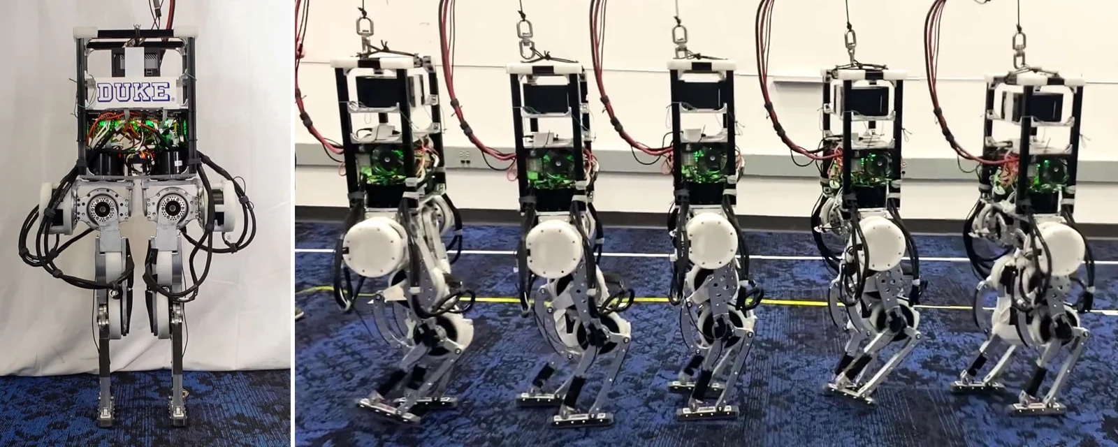
Open-source 10-DOF research biped for energy-efficient RL locomotion exploiting passive dynamics.

- Drawing
- /duke/duke-humanoid
- Maker
- Duke University General Robotics Lab
- Country
- Durham, US
- Package rev
- v0.1.0
- Level
- L1 Compiled
- Availability
- Research only
- Openness
- 85/100
- HW licence
- unknown
- Last checked
- 2026-09-25
- DOF
- 10
Paper arXiv:2409.19795. Hardware wiki on Notion holds the BOM, CNC/DIY CAD zips and Fusion files; the GitHub repo holds code, URDF and policies. The repo is MIT; the Notion CAD has no stated license. v1 is legs only on a box body and tethered (48 V bench supplies, external Linux PC over EtherCAT); motors and drives are quote-only from Motorevo. Repo inactive since Jun 2025; the lab published Duke Humanoid V2 repos in Aug-Sep 2026 (generalroboticslab/duke_humanoid_v2).
Configure
Saved in the URL. Share the link to share the build.Source
One cart across 9 vendors · prices in USD as listed45 lines · 512 parts · 13 without an offer in US · 1/45 lines sourced in 2+ regions (L3 gate)
| # | Part | Category | Qty | Unit | Line | Offer |
|---|---|---|---|---|---|---|
Mouser1 line · unpriced | ||||||
| 1 | MicroStrain 3DM-CV7-AHRS IMU sensor.imu · MPN 3DM-CV7-AHRS | sensor | 1 | unpriced | — | MouserLinked in the Duke BOM |
DigiKey2 lines · unpriced | ||||||
| 2 | TE FX29 compression load cell, 100 lbf, I2C (toe and heel of each foot) sensor.load-cell · MPN FX29K0-100A-0100-L | sensor | 4 | unpriced | — | DigiKeyLinked in the Duke BOM |
| 3 | KEMET ALS70A334QS063 0.33 F capacitor on the distribution block power.capacitor · MPN ALS70A334QS063 | power | 1 | unpriced | — | DigiKeyLinked in the Duke BOM |
PJRC (maker store)1 line · unpriced | ||||||
| 4 | PJRC Teensy 4.0 with pins (sensor hub: IMU over UART, load cells over I2C) electronics.teensy40 | electronics | 1 | unpriced | — | PJRC (maker store) |
Amazon22 lines · unpriced | ||||||
| 5 | Monoprice SlimRun Ethernet patch cable, ~2 m per leg, re-terminated as load-cell extenders cable.load-cell-extender | cable | 2 | unpriced | — | AmazonLinked in the Duke BOM |
| 6 | Pre-crimped MX1.25 male/female connector set (detachable load cells) cable.mx125 | cable | 1 | unpriced | — | AmazonSearch page linked in the Duke Electronics wiki |
| 7 | Latching emergency stop switch on the supplies' remote on/off power.estop | power | 1 | unpriced | — | AmazonLinked in the Duke BOM |
| 8 | Power distribution block (uxcell terminal block) power.distribution-block | power | 1 | unpriced | — | AmazonLinked in the Duke BOM |
| 9 | 12 AWG 3-prong AC power cable, one per supply cable.ac-12awg | cable | 4 | unpriced | — | AmazonSearch page linked in the Duke Electronics wiki |
| 10 | 2020 aluminium extrusion, cut: 4x 353 mm, 2x 260 mm (b), 2x 260 mm (c) structure.extrusion-2020 | structure | 8 | unpriced | — | AmazonLinked in the Duke BOM |
| 11 | 3-way corner connector assembly for 2020 extrusion (top frame) structure.3way-connector | structure | 4 | unpriced | — | AmazonLinked in the Duke BOM |
| 12 | Bearing 65x85x10 mm (hip and knee motor axes) structure.bearing-65x85x10 | structure | 6 | unpriced | — | AmazonLinked in the Duke BOM |
| 13 | Flanged bearing 25x37x7 mm structure.bearing-25x37x7f | structure | 8 | unpriced | — | AmazonLinked in the Duke BOM |
| 14 | Needle bearing 10x14x10 mm (knee/ankle linkage) structure.needle-10x14x10 | structure | 10 | unpriced | — | AmazonLinked in the Duke BOM |
| 15 | M5x25 socket head cap screw (Motor_1 rotor) fastener.m5x25-shcs | fastener | 12 | unpriced | — | AmazonLinked in the Duke BOM |
| 16 | M5x10 button head screw (corner connectors) fastener.m5x10-bhcs | fastener | 48 | unpriced | — | AmazonLinked in the Duke BOM |
| 17 | M5 sliding T-nut for 2020 extrusion fastener.m5-tnut | fastener | 24 | unpriced | — | AmazonLinked in the Duke BOM |
| 18 | M4x25 socket head cap screw (Motor_0 and Motor_2 rotors) fastener.m4x25-shcs | fastener | 24 | unpriced | — | AmazonLinked in the Duke BOM |
| 19 | M4x20 screw (parallel linkage) fastener.m4x20 | fastener | 16 | unpriced | — | AmazonLinked in the Duke BOM |
| 20 | M4 nut (parallel linkage) fastener.m4-nut | fastener | 16 | unpriced | — | AmazonLinked in the Duke BOM |
| 21 | M4x12 button head screw (everything else) fastener.m4x12-bhcs | fastener | 198 | unpriced | — | AmazonLinked in the Duke BOM |
| 22 | M4 and M5 external-tooth lock washers (as needed) fastener.lock-washers | fastener | 1 | unpriced | — | AmazonLinked in the Duke BOM |
| 23 | PTFE lubricant (bearings) other.ptfe-grease | other | 1 | unpriced | — | AmazonLinked in the Duke BOM |
| 24 | CATTONGUE non-abrasive grip tape, 2 in (foot soles) other.grip-tape | other | 1 | unpriced | — | AmazonLinked in the Duke BOM |
| 25 | Filament: PLA (Creality), PLA-CF (Bambu Lab), TPU 95A HF (Polymaker) other.filament | other | 1 | unpriced | — | AmazonLinked in the Duke BOM |
| 26 | Gantry fasteners: M8 sliding T-nuts (18 packs of 20) and M8x1.25x16 SHCS (9 packs of 40) fastener.gantry | fastener | 1 | unpriced | — | AmazonLinked in the Duke BOM |
8BitDo1 line · unpriced | ||||||
| 27 | 8BitDo Ultimate controller with 2.4 GHz adapter (velocity commands) electronics.gamepad | electronics | 1 | unpriced | — | 8BitDoships globallyLinked in the hardware-control README; any pygame gamepad works with changes |
McMaster-Carr1 line · unpriced | ||||||
| 28 | Spacer / thrust washer 18x10x2 mm structure.spacer-18x10x2 | structure | 20 | unpriced | — | McMaster-CarrLinked in the Duke BOM |
Henkel1 line · unpriced | ||||||
| 29 | Loctite 222 low-strength threadlocker other.loctite-222 | other | 1 | unpriced | — | HenkelLinked in the Duke BOM |
Reynolds Advanced Materials1 line · unpriced | ||||||
| 30 | Smooth-On Task 16 casting resin (listed 'for molding') other.task16 | other | 1 | unpriced | — | Reynolds Advanced MaterialsLinked in the Duke BOM |
80/202 lines · unpriced | ||||||
| 31 | 80/20 gantry extrusion: 1x 40-8016 @ 1828.8 mm, 2x 40-8080 @ 1828.8 mm, 2x 40-8080 @ 1524 mm, 4x 40-4080 @ 1219.2 mm (mitred), 2x 40-4080 @ 609.6 mm (mitred) structure.gantry-extrusion | structure | 11 | unpriced | — | 80/20Linked in the Duke BOM |
| 32 | 80/20 gantry plates and brackets: 6x 14105 corner bracket, 4x 40-4325, 4x 40-4328, 4x 40-4365, 12x 40-4362, 4x 40-4330, 8x 40-4331 structure.gantry-plates | structure | 42 | unpriced | — | 80/20Linked in the Duke BOM |
No offer in this region13 lines · unpriced | ||||||
| 33 | Motorevo PA-100-2018 geared motor, 18:1 (rated 40 Nm / 20 A), hip yaw, hip roll, knee actuator.pa100-18 · MPN PA-100-2018 | actuator | 6 | unpriced | — | Offers in CN only |
| 34 | Motorevo PA-100-2020 geared motor, 20:1 (rated 44.8 Nm / 20 A), hip pitch actuator.pa100-20 · MPN PA-100-2020 | actuator | 2 | unpriced | — | Offers in CN only |
| 35 | Motorevo PA-100-2010 geared motor, 10:1 (rated 22.4 Nm / 20 A), ankle actuator.pa100-10 · MPN PA-100-2010 | actuator | 2 | unpriced | — | Offers in CN only |
| 36 | Motor controller assembly (Elmo-based EtherCAT drive, CiA 402), one per motor electronics.motor-controller | electronics | 10 | unpriced | — | Offers in CN only |
| 37 | Samtec FFSD-05-S-05.00-01-N ribbon cable (IMU has no premade leads; solder USB + UART by hand) cable.imu-connector · MPN FFSD-05-S-05.00-01-N | cable | 1 | unpriced | — | No offer found yet |
| 38 | TCA9548A 8-channel I2C multiplexer breakout (FX29 address 0x28 is fixed) electronics.i2c-mux · MPN TCA9548A · 1 alt | electronics | 1 | unpriced | — | No offer found yet |
| 39 | 4.7 kΩ resistor (I2C pull-ups) electronics.r-4k7 | electronics | 8 | unpriced | — | No offer found yet |
| 40 | 220 Ω resistor electronics.r-220 | electronics | 1 | unpriced | — | No offer found yet |
| 41 | 100 nF capacitor (per-device decoupling on the sensor board) electronics.c-100n | electronics | 2 | unpriced | — | No offer found yet |
| 42 | Linux PC, Ubuntu 22.04 + CUDA 12.3, Ethernet port used as EtherCAT master (e.g. enp3s0) compute.host · 1 alt | compute | 1 | unpriced | — | No offer found yet |
| 43 | Mean Well RSP-2000-48 48 V 2000 W supply, 4 in parallel (active current sharing) power.psu · MPN RSP-2000-48 | power | 4 | unpriced | — | No offer found yet |
| 44 | Power wire: 8 AWG (supply outputs), 4 AWG (capacitor), 24 AWG (current-share signals) cable.wire-power | cable | 1 | unpriced | — | No offer found yet |
| 45 | 10 mm external retaining ring (lower leg shafts) structure.retaining-ring-10 | structure | 2 | unpriced | — | No offer found yet |
| Cart total · US | 512 | $0.00 | 45 lines unpriced, not in total | |||
Fabricate
Planned for a 256 mm bed- Fabricated parts
- 90
- Print time (sum)
- —
- Material (sum)
- —
- Plates · estimate
- —
No plate estimate: the package does not list grams per part yet, and we will not guess them. Slice the source files for your 256 mm bed.
| Part | Process | Material | Qty | h / part | g / part | Profile |
|---|---|---|---|---|---|---|
Body plates: 2x B_Shelf_Plate, 1x B_Base_Plate, 12x B_Corner_Connector cnc.body | CNC | Aluminium 6061 | 15 | — | — | source |
Upper leg (hip) plates, 7 per leg: Hip_0 Top/Front/Back/Inner/Outer, Hip_1 Inner/Outer (all symmetric) cnc.upper-leg | CNC | Aluminium 6061 | 14 | — | — | source |
Lower leg parts, 13 per leg: Hip_to_Lower_Connector, Shank_Plate Outer/Inner, Knee_Joint_Holder, Knee_Rocker, Ankle_Rocker, 2x Shank_Ankle_Link, 2x Knee_Link, Shank_Link_Main, Shank_Link_Back, Foot_Main (mirror parts have L and R files) cnc.lower-leg | CNC | Aluminium 6061 | 26 | — | — | source |
Bearing_Load_Shaft cnc.load-shaft | CNC | Aluminium 6061 | 10 | — | — | source |
B_Teensy_Mount and B_IMU_Mount printed.electronics-mounts | FDM | PLA or PLA-CF, 25% adaptive cubic, 2 walls | 2 | — | — | source |
Knee_Stopper (mirror) printed.knee-stopper | FDM | TPU 95A, 30% gyroid, 2 walls | 2 | — | — | source |
Foot_Sole: hard (PLA/PLA-CF, 100% rectilinear) or soft (TPU 95A, 60% adaptive cubic, 0 walls, flow 0.9, ~60-70A) printed.foot-sole | FDM | PLA / PLA-CF or TPU 95A | 2 | — | — | source |
Load_Cell_Enclosure printed.load-cell-enclosure | FDM | PLA-CF, 100% rectilinear, 0.16 mm layers (Bambu Lab printer) | 4 | — | — | source |
Motor protection guards L/R_P_0..P_4 printed.motor-protection | FDM | TPU 95A, 30% gyroid, 0 walls, flow 0.6 | 10 | — | — | source |
Joint zeroing jigs: A_hip_0_2_5_7, A_knee_ankle_3_4_L, A_knee_ankle_8_9_R, A_hip_1_L, A_hip_6_R (one of each design) printed.alignment-jigs | FDM | Not specified | 5 | — | — | source |
Assemble
Every step ends in a check- Steps
- 18
- Subassemblies
- 6
- Hands-on time (sum)
- —
- Critical path
- —
- Your progress · this device
- —
18 steps have no time estimate; times above are lower bounds.
Steps, in build order
- Fabrication01
Order the CNC parts
Download the CNC and DIY STEP zip from the BOM page and order every 'machined' part in Al 6061 (the lab used JLCCNC: ISO 2768 medium, Ra 3.2). Order mirror parts as separate left and right files; symmetric parts use one file for both legs. Holes are tapped by the shop or by you.
CHECKYou have 15 body parts, 14 upper-leg plates, 26 lower-leg parts and 10 load shafts, and an M4 screw threads by hand into every tapped hole.- Parts in
- Body plates: 2x B_Shelf_Plate, 1x B_Base_Plate, 12x B_Corner_Connectorcnc.body
- Upper leg (hip) plates, 7 per leg: Hip_0 Top/Front/Back/Inner/Outer, Hip_1 Inner/Outer (all symmetric)cnc.upper-leg
- Lower leg parts, 13 per leg: Hip_to_Lower_Connector, Shank_Plate Outer/Inner, Knee_Joint_Holder, Knee_Rocker, Ankle_Rocker, 2x Shank_Ankle_Link, 2x Knee_Link, Shank_Link_Main, Shank_Link_Back, Foot_Main (mirror parts have L and R files)cnc.lower-leg
- Bearing_Load_Shaftcnc.load-shaft
- Tools
- —
- Torque
- —
- Time
- —
- After
- Start
- Source
- notion.so
- 02
Print the DIY parts and grip the soles
Print with the per-part settings in the manufacturing table. Apply 2 in grip tape to each foot sole and fuse it with a heat gun at about 300 °F, moving quickly so the printed foot does not deform.
CHECKA FX29 load cell drops into each enclosure with its button proud of the surface, and the grip tape does not lift at the edges when flexed.- Parts in
- B_Teensy_Mount and B_IMU_Mountprinted.electronics-mounts
- Knee_Stopper (mirror)printed.knee-stopper
- Foot_Sole: hard (PLA/PLA-CF, 100% rectilinear) or soft (TPU 95A, 60% adaptive cubic, 0 walls, flow 0.9, ~60-70A)printed.foot-sole
- Load_Cell_Enclosureprinted.load-cell-enclosure
- Motor protection guards L/R_P_0..P_4printed.motor-protection
- Joint zeroing jigs: A_hip_0_2_5_7, A_knee_ankle_3_4_L, A_knee_ankle_8_9_R, A_hip_1_L, A_hip_6_R (one of each design)printed.alignment-jigs
- Filament: PLA (Creality), PLA-CF (Bambu Lab), TPU 95A HF (Polymaker)other.filament
- CATTONGUE non-abrasive grip tape, 2 in (foot soles)other.grip-tape
- Tools
- FDM printer (lab used Bambu Lab X1C and Prusa MK4), Smooth PEI (PLA) and textured PEI (TPU) sheets, Heat gun
- Torque
- —
- Time
- —
- After
- Start
- Source
- notion.so
- Test rig03
Build the 80/20 test gantry
Build the frame from the 80/20 extrusions (mitred 4080 members per the provided drawing) and plates. The robot hangs from it for dynamics matching and first walking.
CHECKThe frame stands without rocking and a hanging robot's feet clear the floor with room for a full leg swing.- Parts in
- 80/20 gantry extrusion: 1x 40-8016 @ 1828.8 mm, 2x 40-8080 @ 1828.8 mm, 2x 40-8080 @ 1524 mm, 4x 40-4080 @ 1219.2 mm (mitred), 2x 40-4080 @ 609.6 mm (mitred)structure.gantry-extrusion
- 80/20 gantry plates and brackets: 6x 14105 corner bracket, 4x 40-4325, 4x 40-4328, 4x 40-4365, 12x 40-4362, 4x 40-4330, 8x 40-4331structure.gantry-plates
- Gantry fasteners: M8 sliding T-nuts (18 packs of 20) and M8x1.25x16 SHCS (9 packs of 40)fastener.gantry
- Tools
- Hex keys
- Torque
- —
- Time
- —
- After
- Start
- Source
- notion.so
- Legs04
Upper legs: hip yaw, roll and pitch
Follow the upper-leg assembly video for each leg. Motor_1 rotor takes M5x25, Motor_0 rotor M4x25, everything else M4x12. Use a sesame-seed amount of Loctite 222; excess threadlocker can damage the motors.
CHECKEach hip axis turns by hand through its range with no binding and no axial play at the 65x85x10 bearings.- Parts in
- Upper leg (hip) plates, 7 per leg: Hip_0 Top/Front/Back/Inner/Outer, Hip_1 Inner/Outer (all symmetric)cnc.upper-leg
- Motorevo PA-100-2018 geared motor, 18:1 (rated 40 Nm / 20 A), hip yaw, hip roll, kneeactuator.pa100-18
- Motorevo PA-100-2020 geared motor, 20:1 (rated 44.8 Nm / 20 A), hip pitchactuator.pa100-20
- Bearing 65x85x10 mm (hip and knee motor axes)structure.bearing-65x85x10
- Flanged bearing 25x37x7 mmstructure.bearing-25x37x7f
- M5x25 socket head cap screw (Motor_1 rotor)fastener.m5x25-shcs
- M4x25 socket head cap screw (Motor_0 and Motor_2 rotors)fastener.m4x25-shcs
- M4x12 button head screw (everything else)fastener.m4x12-bhcs
- Loctite 222 low-strength threadlockerother.loctite-222
- PTFE lubricant (bearings)other.ptfe-grease
- Tools
- Hex keys (wiki recommends Bondhus)
- Torque
- —
- Time
- —
- After
- 01
- Source
- notion.so
- 05
Lower legs: knee and ankle parallel linkage
Follow the lower-leg video: mount Motor_3 (knee) and Motor_4 (ankle) with M4x12, Motor_2 rotor with M4x25, and build the knee and shank-ankle linkages on M4x20 screws and nuts with needle bearings and spacers.
CHECKKnee and ankle move through their range by hand with no play in the linkage, and the knee stopper stops hyperextension.- Parts in
- Lower leg parts, 13 per leg: Hip_to_Lower_Connector, Shank_Plate Outer/Inner, Knee_Joint_Holder, Knee_Rocker, Ankle_Rocker, 2x Shank_Ankle_Link, 2x Knee_Link, Shank_Link_Main, Shank_Link_Back, Foot_Main (mirror parts have L and R files)cnc.lower-leg
- Bearing_Load_Shaftcnc.load-shaft
- Motorevo PA-100-2018 geared motor, 18:1 (rated 40 Nm / 20 A), hip yaw, hip roll, kneeactuator.pa100-18
- Motorevo PA-100-2010 geared motor, 10:1 (rated 22.4 Nm / 20 A), ankleactuator.pa100-10
- Bearing 65x85x10 mm (hip and knee motor axes)structure.bearing-65x85x10
- Flanged bearing 25x37x7 mmstructure.bearing-25x37x7f
- Needle bearing 10x14x10 mm (knee/ankle linkage)structure.needle-10x14x10
- Spacer / thrust washer 18x10x2 mmstructure.spacer-18x10x2
- 10 mm external retaining ring (lower leg shafts)structure.retaining-ring-10
- M4x25 socket head cap screw (Motor_0 and Motor_2 rotors)fastener.m4x25-shcs
- M4x20 screw (parallel linkage)fastener.m4x20
- M4 nut (parallel linkage)fastener.m4-nut
- M4x12 button head screw (everything else)fastener.m4x12-bhcs
- Knee_Stopper (mirror)printed.knee-stopper
- Loctite 222 low-strength threadlockerother.loctite-222
- Tools
- —
- Torque
- —
- Time
- —
- Source
- notion.so
- Body06
Base plate: hip motors, IMU, sensor-board mount
Screw the hip 0/5 motors (20:1 and 18:1) to the top side of the base plate with M4x12, using very little Loctite. Seat the IMU on its mount with the cable in the channel, centre it with the wired side facing forward, and push it onto the plate pegs. Tap and fit the PCB mount, then stand an extrusion in each corner with corner brackets, M5 screws and sliders.
CHECKThe IMU is on the robot centreline with its cable side forward, and the four corner extrusions are square to the plate.- Parts in
- Body plates: 2x B_Shelf_Plate, 1x B_Base_Plate, 12x B_Corner_Connectorcnc.body
- B_Teensy_Mount and B_IMU_Mountprinted.electronics-mounts
- MicroStrain 3DM-CV7-AHRS IMUsensor.imu
- 2020 aluminium extrusion, cut: 4x 353 mm, 2x 260 mm (b), 2x 260 mm (c)structure.extrusion-2020
- M4x12 button head screw (everything else)fastener.m4x12-bhcs
- M5x10 button head screw (corner connectors)fastener.m5x10-bhcs
- M5 sliding T-nut for 2020 extrusionfastener.m5-tnut
- M4 and M5 external-tooth lock washers (as needed)fastener.lock-washers
- Tools
- —
- Torque
- —
- Time
- —
- Source
- notion.so
- Legs07
Feet with toe and heel load cells
Seat the sensor holders in the empty foot, line the foot holes up with the aluminium, insert each load cell with the ridge aligned, then screw the foot on with Loctite. Do not overtighten; it can damage the force sensors.
CHECKThe foot sits flat on a table, and pressing each corner deflects only the load-cell button, not the sole.- Parts in
- Foot_Sole: hard (PLA/PLA-CF, 100% rectilinear) or soft (TPU 95A, 60% adaptive cubic, 0 walls, flow 0.9, ~60-70A)printed.foot-sole
- Load_Cell_Enclosureprinted.load-cell-enclosure
- TE FX29 compression load cell, 100 lbf, I2C (toe and heel of each foot)sensor.load-cell
- Lower leg parts, 13 per leg: Hip_to_Lower_Connector, Shank_Plate Outer/Inner, Knee_Joint_Holder, Knee_Rocker, Ankle_Rocker, 2x Shank_Ankle_Link, 2x Knee_Link, Shank_Link_Main, Shank_Link_Back, Foot_Main (mirror parts have L and R files)cnc.lower-leg
- Tools
- —
- Torque
- —
- Time
- —
- After
- 05
- Source
- notion.so
- Body09
Middle plate: motor controllers
Mount two motor controllers per controller plate with heat conduction to the plate, fit the power and ground splitters in the middle, tap the middle plate and fix the controller plates without overtightening. Slide the plate onto the extrusions with the controllers facing down, leaving room for the top plate.
CHECKAll ten controllers are fixed, cable-tied, and their EtherCAT and power ports are reachable.- Parts in
- Body plates: 2x B_Shelf_Plate, 1x B_Base_Plate, 12x B_Corner_Connectorcnc.body
- Motor controller assembly (Elmo-based EtherCAT drive, CiA 402), one per motorelectronics.motor-controller
- M5x10 button head screw (corner connectors)fastener.m5x10-bhcs
- M5 sliding T-nut for 2020 extrusionfastener.m5-tnut
- Tools
- —
- Torque
- —
- Time
- —
- After
- 06
- Source
- notion.so
- 10
Top plate and top frame
Fit the top plate on corner brackets and sliders (an onboard Jetson is optional and goes between the plates). Build the rectangular top frame from 3-way connectors and slide it onto the body.
CHECKThe body is rigid when twisted by hand and the top frame can take the gantry hook.- Parts in
- Body plates: 2x B_Shelf_Plate, 1x B_Base_Plate, 12x B_Corner_Connectorcnc.body
- 3-way corner connector assembly for 2020 extrusion (top frame)structure.3way-connector
- 2020 aluminium extrusion, cut: 4x 353 mm, 2x 260 mm (b), 2x 260 mm (c)structure.extrusion-2020
- M5x10 button head screw (corner connectors)fastener.m5x10-bhcs
- M5 sliding T-nut for 2020 extrusionfastener.m5-tnut
- Tools
- —
- Torque
- —
- Time
- —
- After
- 09
- Source
- notion.so
- Electrical11
Sensor board: Teensy, I2C mux, IMU and load-cell leads
Hand-solder the IMU ribbon (wire 1 is red) to USB and UART. Make one Ethernet extender per leg carrying two load cells on MX1.25 connectors using the wiki's colour map. Keep every load-cell I2C line separate into its own TCA9548A channel, give every device its own decoupling capacitor, and connect the mux to the Teensy I2C pins.
CHECKContinuity on every extender wire; with one load cell on a Linux I2C bus, `i2cdetect -y <bus>` shows 0x28.- Parts in
- PJRC Teensy 4.0 with pins (sensor hub: IMU over UART, load cells over I2C)electronics.teensy40
- TCA9548A 8-channel I2C multiplexer breakout (FX29 address 0x28 is fixed)electronics.i2c-mux
- 4.7 kΩ resistor (I2C pull-ups)electronics.r-4k7
- 220 Ω resistorelectronics.r-220
- 100 nF capacitor (per-device decoupling on the sensor board)electronics.c-100n
- Samtec FFSD-05-S-05.00-01-N ribbon cable (IMU has no premade leads; solder USB + UART by hand)cable.imu-connector
- Monoprice SlimRun Ethernet patch cable, ~2 m per leg, re-terminated as load-cell extenderscable.load-cell-extender
- Pre-crimped MX1.25 male/female connector set (detachable load cells)cable.mx125
- MicroStrain 3DM-CV7-AHRS IMUsensor.imu
- TE FX29 compression load cell, 100 lbf, I2C (toe and heel of each foot)sensor.load-cell
- Tools
- Soldering iron, Multimeter
- Torque
- —
- Time
- —
- Source
- notion.so
- 12
48 V supply bank, e-stop and bus capacitor
Safety · human-verified requiredWire four RSP-2000-48 supplies in parallel per the Mean Well datasheet: 12 AWG AC input (check your cable's colours), 24 AWG current-share signals, 8 AWG outputs to the distribution block, the e-stop on each supply's remote on/off, and the 0.33 F capacitor on the block with 4 AWG. Keep the motor controllers disconnected.
CHECKWith controllers unplugged: the block reads about 48 V with correct polarity, and pressing the e-stop drops it to 0 V on all four supplies.This step can hurt a person or ruin parts. Its instructions need sign-off by a human who has done it before relying on them. Stop and ask if anything differs from what you see.
- Parts in
- Mean Well RSP-2000-48 48 V 2000 W supply, 4 in parallel (active current sharing)power.psu
- Latching emergency stop switch on the supplies' remote on/offpower.estop
- KEMET ALS70A334QS063 0.33 F capacitor on the distribution blockpower.capacitor
- Power distribution block (uxcell terminal block)power.distribution-block
- 12 AWG 3-prong AC power cable, one per supplycable.ac-12awg
- Power wire: 8 AWG (supply outputs), 4 AWG (capacitor), 24 AWG (current-share signals)cable.wire-power
- Tools
- Crimp tool, Multimeter
- Torque
- —
- Time
- —
- After
- 09
- Source
- notion.so
- 13
EtherCAT chain and host
Safety · human-verified requiredDaisy-chain the ten controllers in the wiki's topology order to the host's Ethernet port, then power the bus from the supply bank with the robot hanging on the gantry.
CHECK`sudo ./ext/SOEM/test/linux/slaveinfo/slaveinfo enp3s0 -sdo` lists 10 slaves.This step can hurt a person or ruin parts. Its instructions need sign-off by a human who has done it before relying on them. Stop and ask if anything differs from what you see.
- Parts in
- Motor controller assembly (Elmo-based EtherCAT drive, CiA 402), one per motorelectronics.motor-controller
- Linux PC, Ubuntu 22.04 + CUDA 12.3, Ethernet port used as EtherCAT master (e.g. enp3s0)compute.host
- Tools
- SOEM slaveinfo
- Torque
- —
- Time
- —
- Source
- notion.so
- Bring-up14
Load and match the drive configurations
Safety · human-verified requiredFor each joint pair, import the published .gprm file (motor0 to motor4 pages) under Expert Tuning > Axis Configuration > Import Page Parameters, then finalise current, velocity and position loops. Tune one motor of each pair and copy its configuration to the other leg.
CHECKLeft and right motors of each pair track the same position trajectory with overlapping plots in Elmo.This step can hurt a person or ruin parts. Its instructions need sign-off by a human who has done it before relying on them. Stop and ask if anything differs from what you see.
- Parts in
- Motor controller assembly (Elmo-based EtherCAT drive, CiA 402), one per motorelectronics.motor-controller
- Motorevo PA-100-2018 geared motor, 18:1 (rated 40 Nm / 20 A), hip yaw, hip roll, kneeactuator.pa100-18
- Motorevo PA-100-2020 geared motor, 20:1 (rated 44.8 Nm / 20 A), hip pitchactuator.pa100-20
- Motorevo PA-100-2010 geared motor, 10:1 (rated 22.4 Nm / 20 A), ankleactuator.pa100-10
- Tools
- Elmo Application Studio II (Windows)
- Torque
- —
- Time
- —
- After
- 13
- Source
- notion.so
- 15
Build host software and flash the Teensy
Clone DukeHumanoidv1 with submodules, create the py38 environment, build the SOEM-based ethercat_motor_py extension with CMake, and upload teensy_comm.ino with the TCA9548 and Packetizer libraries. In MicroStrain SensorConnect set the IMU to 921600 baud and save without 'sample on startup'.
CHECK`sudo chrt -f 99 $(which python) -u sensor_controller.py` streams IMU orientation and four load-cell readings (unloaded values inside the FX29's 300-1700 count zero band).- Parts in
- Linux PC, Ubuntu 22.04 + CUDA 12.3, Ethernet port used as EtherCAT master (e.g. enp3s0)compute.host
- PJRC Teensy 4.0 with pins (sensor hub: IMU over UART, load cells over I2C)electronics.teensy40
- Tools
- micromamba, vcpkg (msgpack, eigen3, iir1), CMake + GCC 12, Arduino IDE + Teensyduino
- Torque
- —
- Time
- —
- Source
- github.com
- 16
Joint initialization with the alignment jigs
Safety · human-verified requiredConstrain every joint in its zero pose with the hip, thigh and ankle jigs, then run motor_controller.py, which records the encoder offsets per motor. This is needed after every power-on, because the encoder position repeats once per reduction-ratio sector.
CHECKAfter removing the jigs, `trajectory_PD_test.py` holds the robot in the zero configuration, standing with straight knees.This step can hurt a person or ruin parts. Its instructions need sign-off by a human who has done it before relying on them. Stop and ask if anything differs from what you see.
- Parts in
- Joint zeroing jigs: A_hip_0_2_5_7, A_knee_ankle_3_4_L, A_knee_ankle_8_9_R, A_hip_1_L, A_hip_6_R (one of each design)printed.alignment-jigs
- Tools
- —
- Torque
- —
- Time
- —
- Source
- notion.so
- 17
Sim-to-real trajectory matching on the gantry
With the robot hanging, run `bash run.sh match_dyn` in legged_env, `trajectory_PD_test.py` on the robot and `sshkeyboard_pd_test.py` to drive both, then compare /sim and /real in PlotJuggler and adjust armature, friction and damping.
CHECKJoint position traces for /sim and /real overlap for every joint through a keyboard-commanded trajectory.- Parts in
- —
- Tools
- PlotJuggler (msgpack, port 9870)
- Torque
- —
- Time
- —
- Source
- notion.so
- 18
Run the published walking policy
Safety · human-verified requiredRun `biped_controller.py` with the baseline or passive ONNX checkpoint and `gamepad.py` in a second terminal. Start on the gantry with a hand on the e-stop.
CHECKThe robot walks forward and stops on gamepad command without falling for 30 s, with the gantry line slack.This step can hurt a person or ruin parts. Its instructions need sign-off by a human who has done it before relying on them. Stop and ask if anything differs from what you see.
- Parts in
- 8BitDo Ultimate controller with 2.4 GHz adapter (velocity commands)electronics.gamepad
- Tools
- —
- Torque
- —
- Time
- —
- After
- 17
- Source
- github.com
Progress is stored in this browser only (localStorage). Nothing is sent anywhere.
Bring-up
Flash · calibrate · first policy- A
Flash firmware
Targetsteensy_comm (Teensy 4.0 sensor hub), Elmo drive parameters (.gprm per joint pair), ethercat_motor_py (host EtherCAT master, SOEM)
Repogithub.com/generalroboticslab/dukeHumanoidHardwareControl
Host runs Ubuntu 22.04 with a real-time priority Python loop (`sudo chrt -f 99`). The Teensy streams CRC-checked Packetizer frames at 1.5 Mbaud; the IMU runs on Serial1 at 921600. Drive tuning notes (kp/ki per pair) are on the motor0-motor4 wiki pages.
- B
Calibrate
CalibrationJoint initialization with printed alignment jigs on every power-on (motor_controller.py stores offsets); IMU baud, gyro bias and mounting transform via MicroStrain SensorConnect.Log the output. It goes in your build report.
- C
First policy
- walk, velocity tracking (baseline)Isaac Gym + rl_games (legged_env) source
- walk, energy-efficient passive-dynamics policyIsaac Gym + rl_games (legged_env) source
- walk (training checkpoints)Isaac Gym + rl_games source
Try the policy in the browser sim before it touches hardware. Keep a hand near the power switch the first time a policy runs on the real robot.
Report your build
Moves Duke Humanoid v1 toward L4 · BuiltA build report is the only thing that proves a package works. It raises the level, puts a point on the map, and tells the Foreman which steps to rewrite.
Level gate
Holds L1 · evidence, not confidence- L0Indexed
Known to exist. Atlas page only.
- 4 sources on record(met)
- L1Compiled
Package validates against the spec; every fact has a source.
- Build package compiled(met)
- 14 sources across robot and package(met)
- L2Sim-verified
Loads in browser and GPU sim, mass within tolerance of the BOM, holds a stand. Unlocks .training.
- URDF/MJCF is public(met)
- Sim load, mass tolerance and stand are checked on .training(checked elsewhere)
- L3Sourced
Every BOM line resolves to a live offer in at least two regions. Unlocks the one-click cart.
- 0/45 BOM lines have offers in 2+ regions(not met)
- L4Built
At least one community build report with photos and bring-up logs. Unlocks Build it as the main action.
- 0 reviewed build reports(not met)
- Review feed unreachable at last refresh; count is registry-only(checked elsewhere)
- L5Certified
The robot's maintainer signs the package. Unlocks certified teams and kit sales.
- Maintainer signature not recorded(not met)
Levels are cumulative and set by the registry from reviewed evidence. This panel shows what can be measured from the package today.
Same robot, other verbs
Revisions and sources
Every fact on this sheet traces to one of these| Rev | Description | Checked |
|---|---|---|
| PKG | Build package, current revision 0.1.0 | — |
| S1 | Official repogithub.com | 2026-09-24 |
| S2 | arXiv paperarxiv.org | 2026-09-24 |
| S3 | Duke Humanoid V1 hardware wiki (Notion: BOM, CAD, power, EtherCAT)app.notion.com | 2026-09-25 |
| S4 | duke_humanoid_v2 repo (created 2026-08-25)github.com | 2026-09-25 |
| S5 | Duke Humanoid V1 hardware wiki (Notion)notion.so | 2026-09-25 |
| S6 | Wiki: Bill of Materials (+ BOM.xlsx, CNC_and_DIY_Files.zip, Fusion .f3z)notion.so | 2026-09-25 |
| S7 | Wiki: Manufacturing & Assemblynotion.so | 2026-09-25 |
| S8 | Wiki: Electronics (power, motors, EtherCAT, IMU, load cells)notion.so | 2026-09-25 |
| S9 | Wiki: Deployment (joint initialization, trajectory matching)notion.so | 2026-09-25 |
| S10 | DukeHumanoidv1 (parent repo, MIT)github.com | 2026-09-25 |
| S11 | dukeHumanoidHardwareControlgithub.com | 2026-09-25 |
| S12 | legged_env (Isaac Gym training, URDF, checkpoints)github.com | 2026-09-25 |
| S13 | Paper: The Duke Humanoid (arXiv 2409.19795)arxiv.org | 2026-09-25 |
| S14 | Mean Well RSP-2000 datasheetmeanwellusa.com | 2026-09-25 |